ABB M4M 20 Modbus
Power and energy meter
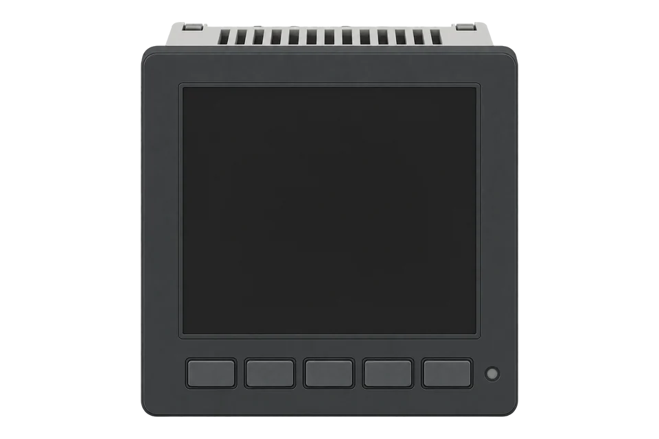
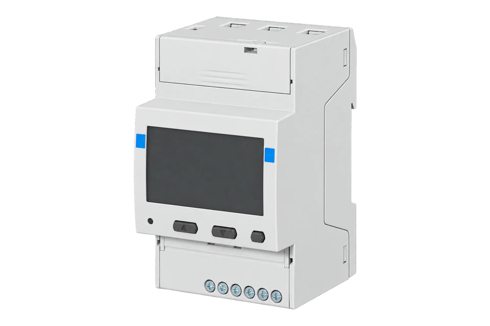
M4M 20 Modbus, order 2CSG251141R4051, measures a single- or three-phase circuit through conventional 1 A or 5 A CTs. It provides live electrical readings, import/export energy, THD and basic demand values. This exact version has two digital outputs and RS-485; the Ethernet, Rogowski, I/O and MID versions are different products.
- Modbus RTU
Power and energy meter
Compatibility
Compatible through Modbus RTU
ABB documents RS-485 Modbus RTU measurement reads with literal addresses, integer types and scaling.
M4M 20 MODBUS, 2CSG251141R4051 (M4M20RS485), with conventional CT inputs. Use the workbook’s M4M 20 applicability as the starting point. The voltage, current, power and energy points below are supported for both M4M 20 and M4M 30; additional power-quality rows may be model-specific. Reject unavailable values before scaling and compare readings with the display.
Connect it with
-
Modbus Interface ZMB-3XFrom €399 ex VAT Configure Modbus Interface
-
Gateway ZGW-20From €899 ex VAT Configure Gateway


For exact M4M20RS485 with its configured serial address
- Modbus
- Wireless
- Edge
- Platforms
Models
| Models | Interface | Route into Edge |
|---|---|---|
| M4M 20 Modbus · 2CSG251141R4051 | Conventional1 A/5 A CT inputs; two digital outputs; Modbus RTU and Bluetooth | RS-485 is the documented measurement route in this guide. |
| M4M 20 Ethernet / BACnet / Profibus | Different communications variants, despite a similar front panel | Do not assume the RS-485 variant has an Ethernet port or BACnet/IP. |
| M4M 20 I/O / Rogowski / M4M20-M | Additional I/O, different current sensor input or MID-specific specification | Use the exact hardware manual and relevant map applicability; no variant equivalence is claimed. |
| M4M 30 Modbus | Separate analyser with four programmable I/O and additional model-specific quantities | Compare the reviewed M4M30 guide if those functions matter; shared register addresses do not make the hardware identical. |
Specifications
The standard Modbus version combines conventional CT metering with two digital outputs. Its manual describes basic demand and minimum/maximum demand, 25 single alarms and 32 MB flash. It is useful for panel energy monitoring without assuming the extra I/O or M4M30-only power-quality quantities in the combined register workbook.13
- Exact order code
- 2CSG251141R4051 / M4M20RS4854
- Current measurement
- Three conventional CT inputs; 1 A or 5 A secondary ; 50 mA–6 A measurement range without accuracy derating. Neutral current is calculated.1
- Voltage and supply
- 46–400 VAC L-N and 80–690 VAC L-L measurement range, with the manual’s stated conditions; separate 48–240 VAC/DC auxiliary supply ±15%.1
- Energy accuracy
- Active energy class 0.5S to IEC 62053-22 under the specified conditions. CT errors and installation errors are additional; this is not a MID claim.1
- Serial interface
- Optically isolated RS-485; address 1–247; 9.6, 19.2, 38.4, 57.6 or 115.2 kbit/s; configurable parity and stop bits.1
- I/O and analysis
- Two digital outputs; basic demand; THD; true-RMS measurement up to the 40th harmonic. Do not infer M4M30-only register support.13
- Installation envelope
- Indoor panel mounting; front IP54, terminals IP20; operating −25 to +70 °C and up to 93% relative humidity, non-condensing at 40 °C.1
Interface
Documented measurements and integration boundaries for M4M 20 Modbus.
- L1 phase voltage: literal 0x5B02, unsigned 32-bit integer, resolution 0.1 V.
- Phase currents, powers, frequency and power factor, decoded using each map row’s width, sign and resolution.
- Import and export energy are separate counters. Import active energy at 0x5000 occupies four registers with 0.01 kWh resolution.
- THD, basic demand and minimum/maximum values supported by M4M20; check the product-applicability column before adding a family-map quantity.
- Unavailable unsigned quantities use FFFF in every register; signed quantities use the maximum positive code for their width. These are missing readings, not consumption.
Assessment
M4M 20 MODBUS, 2CSG251141R4051 (M4M20RS485), with conventional CT inputs. Use the workbook’s M4M 20 applicability as the starting point. The voltage, current, power and energy points below are supported for both M4M 20 and M4M 30; additional power-quality rows may be model-specific. Reject unavailable values before scaling and compare readings with the display.
- InteroperabilityWell supported
- Manufacturer protocol manual plus typed, scaled register workbook establish a complete local read path.23
- AccuracySupported with conditions
- Conventional CT inputs and class 0.5S active-energy measurement have defined conditions; CT and wiring error remain separate.1
- SecuritySupported with conditions
- The user manual documents password-controlled configuration; protect the serial segment and omit writes from monitoring.1
- ReliabilitySupported with conditions
- The manual defines 48–240VAC/DC auxiliary supply with ±15% tolerance, non-condensing conditions and a measurement refresh interval. These are installation limits, not evidence of a tested field uptime.1
- RuggednessSupported with conditions
- IP54 front, IP20 terminals and −25 to +70 °C operating range define a panel-mounted installation envelope.1
Setup
Read and scale L1 phase voltage
ABB’s communications manual gives the FC03 request at 0x5B02, and its mapping workbook defines the two-register unsigned value with 0.1 V resolution.
- Function
- FC03 Read Holding Registers
- Literal PDU address
- 0x5B02 = 23298 decimal; this is already the bus address
- Quantity
- 2 registers, 4 data bytes
- Request PDU
- 03 5B 02 00 02; the RTU client adds the configured slave address and CRC
- Synthetic response data
- 00 00 08 FC, most significant byte first
- Decode
- Unsigned 32-bit 2300 × 0.1 V = 230.0 V
- Acceptance
- Confirm the configured wiring supports L1-N, then compare the scaled value with the simultaneous meter display
Acceptance: The 230 V response is an independently calculated example, not a physical device capture. Never apply the 0.1 multiplier to every register: current, power, energy and status entries have their own type, width and resolution.
-
Match the order code and CT input
Confirm 2CSG251141R4051 and record firmware and map revision. The conventional-CT inputs require the installed 1 A or 5 A secondary and correct primary ratio. Have the authorised installer confirm phase assignment and the selected wiring system before comparing readings.
-
Record the actual serial settings
Open Configuration, Communication, Modbus RTU and record the address, speed, parity and stop bits. Match them in the Edge serial connection. Keep one master on the RS-485 segment and follow ABB’s bus wiring and end-termination instructions.
-
Use literal addresses and complete values
ABB’s Start Reg Hex is the address sent on the bus. Convert hex to decimal if the client requires it; do not subtract one. Read both registers of L1 voltage at 0x5B02 in one FC03 request.
-
Decode before expanding the point list
Apply unsigned 32-bit decoding, most significant byte first, and the 0.1 V resolution for the voltage example. Compare the result with the meter display, then configure each further quantity from its own type, register count and resolution.
-
Add supported measurements, not the whole family map
After voltage, add L1 current at 0x5B10 (23312), two unsigned registers × 0.01 A; total active power at 0x5B1A (23322), two signed registers × 0.01 W; and active import/export energy at 0x5000/0x5004 (20480/20484), four unsigned registers each × 0.01 kWh. Use FC03 and high-word-first integer decoding. ABB allows 1–125 registers per read; start with complete values and group nearby points. Reject unavailable raw markers before scaling. Keep configuration, reset and historical-selection writes separate.
Common questions
- Should 0x5B02 become 23297?
- No. ABB states that the hexadecimal start register is expressed exactly as sent on the bus. 0x5B02 is decimal 23298; no one-based correction is applied.2
- Why does a float decoder give nonsense?
- L1 phase voltage is an unsigned integer across two registers, with 0.1 V resolution. Reinterpretation as IEEE-754 FLOAT32 changes the meaning of those bits. Use the workbook’s data type and multiplier.3
- Does the shared M4M workbook mean every register works on M4M20?
- No. The product-applicability column distinguishes model-dependent functions. The M4M20 manual describes basic demand and THD, while the workbook contains additional rows limited to M4M30. Select supported quantities rather than importing the entire family table.13
- Does Bluetooth replace the RS-485 connection?
- The exact product offers Bluetooth and Modbus RTU, but this Edge integration uses the documented RS-485 Modbus interface. Bluetooth commissioning is not a claim of an Edge Bluetooth driver.14
- How is this different from M4M30 Modbus?
- The standard M4M20 Modbus has two digital outputs and basic demand functions. The reviewed M4M30 Modbus has four programmable I/O and additional analyser quantities. Choose by the functions required at the panel, then verify the exact order code and map applicability.135
- How do I handle unavailable measurements?
- For unsigned quantities, reject all FFFF words. For signed quantities, reject the maximum positive integer for that width, such as 0x7FFFFFFF for two registers. Check the raw value before applying its scale and store unavailable as missing, not zero. These markers distinguish unsupported points from valid measurements.2
Related devices


Sources
- M4M 20 user manual, 2CSG445032D0201 revision L (opens in a new tab)
- M4M Modbus communication protocol, 2CSG445050D0201 (opens in a new tab)
- M4M Modbus mapping workbook, 9AKK107492A7627 revision F download (opens in a new tab)
- M4M20RS485 official product record, 2CSG251141R4051 (opens in a new tab)
- M4M 30/32 user manual, 2CSG445042D0201 (opens in a new tab)
Further reading
- ToolModbus register address translator
- ToolModbus register decoder
- GuideM4M 30 Modbus: compare I/O and analyser functions
- GuideABB M4M family register overview
- ToolRS-485 termination and bias
- GuideModbus RS-485 commissioning
- ManufacturerABB devices
- ProtocolModbus devices and register maps
- CategoryEnergy meters
Product names and trademarks belong to their owners. Publication does not imply endorsement or a commercial relationship.