Accuenergy Acuvim 3
Power quality analyser
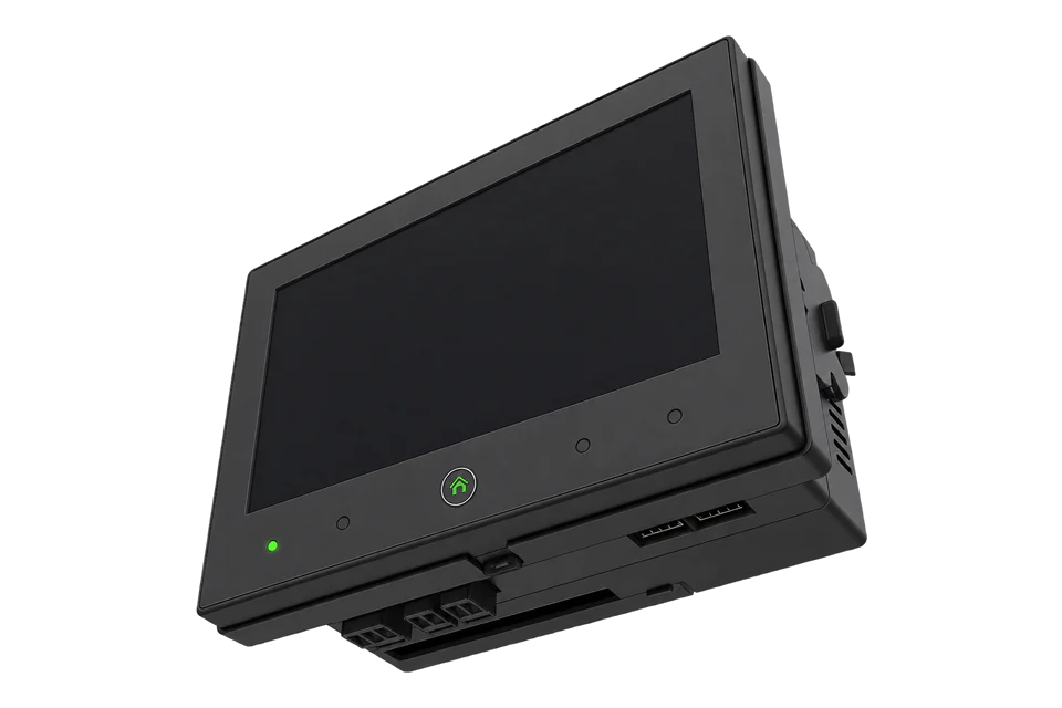
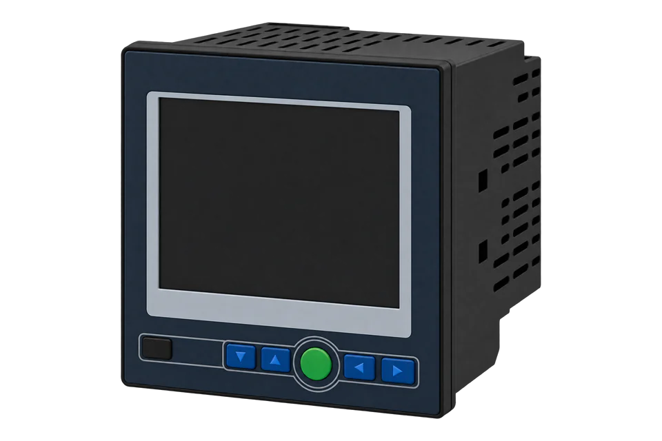
The Acuvim 3 is Accuenergy's power quality meter, certified to IEC 61000-4-30 Class A and rated class 0.1S for active energy. It comes as a panel meter with a 7 inch colour touch screen (D) or a DIN-rail unit without a display (M), for 5 A/1 A CTs or 333 mV and Rogowski coil sensors. Two Ethernet ports run Modbus TCP on port 502 and BACnet/IP, and the RS-485 port runs Modbus RTU at 115200 bit/s 8N1 by default. Accuenergy's Modbus map version 1.00 groups real-time values by update rate: the 200 ms block holds frequency, voltage, current, power and power factor as 32-bit floats from 0x2114. Accumulated energy is published only as 64-bit double or Int64 registers, so Edge reads energy as BACnet/IP Analog Inputs 2056 and 2064 in kWh.
Compatibility
Compatible with EpiSensor Edge over Modbus TCP and BACnet/IP, or Modbus RTU
The Acuvim 3 is compatible with EpiSensor Edge over Modbus TCP on either Ethernet port, or Modbus RTU on its RS-485 port, for real-time measurements, and over BACnet/IP for accumulated energy. Accuenergy publishes the Modbus address table with hexadecimal and decimal addresses, data types and units in the parameter names, and a BACnet points list with object numbers and engineering units.
Acuvim 3 meters, panel (D) or DIN-rail (M), using Modbus address table version 1.00, user manual V 1.0.13 and the BACnet points list for firmware v1.04p13 as a best-effort starting point. The map does not state the word order of its floats: site check by reading frequency at 0x2114 and comparing it with the display before adding points. Read-only monitoring: no writes to the reset or reboot commands.
Connect it with


For most sites: the meter has two Ethernet ports and serves Modbus TCP on port 502
- Modbus
- Edge
- Platforms
For accumulated energy, which the Modbus map publishes only as 64-bit values
- BACnet
- Edge
- Platforms
Where the meter has no network connection
- Modbus
- Wireless
- Edge
- Platforms
Models
| Models | Interface | Route into Edge |
|---|---|---|
| Acuvim-3-D, 5A or mV, P1 or P2 | Panel mount with the 7 inch touch screen display, IP54 at the front; dual Ethernet (ETH1, ETH2), RS-485, USB-C, IRIG-B, four digital I/O and optional Wi-Fi | Modbus TCP on ETH1 or ETH2 for real-time values, BACnet/IP for energy. |
| Acuvim-3-M, 5A or mV, P1 or P2 | DIN-rail mount without a display, IP30, the same ports and map; optional ACUVIM-3-REM-DISP remote display | Same Modbus TCP and BACnet/IP routes. |
| Order code suffixes -MC and -NW, for example Acuvim-3-M-5A-P1-NW and Acuvim-3-D-5A-P2-MC | MC: Measurement Canada applications, not available with the mV current input. NW: no Wi-Fi radio. P1: 100 to 415 V AC, 50/60 Hz, 100 to 300 V DC; P2: 20 to 60 V DC. | The suffixes do not change the wired Modbus TCP, RTU or BACnet/IP paths. |
Specifications
The Acuvim 3 measures three-phase and single-phase systems through external current transformers or sensors, with a fourth current input for measured neutral current. It is a power quality instrument certified to IEC 61000-4-30 Class A, with flicker to IEC 61000-4-15, harmonics to the 127th, waveform capture and EN 50160 and IEEE 519 reports.4
- Order code
- Acuvim-3, then mounting (D: panel mount with LCD display; M: DIN-rail mount without LCD), current input (5A: 5 A/1 A; mV: 333 mV and Rogowski coil), power supply (P1: 100 to 415 V AC, 50/60 Hz, 100 to 300 V DC; P2: 20 to 60 V DC), then optional MC (Measurement Canada) and NW (no Wi-Fi). Examples: Acuvim-3-M-5A-P1-NW, Acuvim-3-D-5A-P2-MC.4
- Voltage inputs
- 400 V AC L-N and 690 V AC L-L nominal full scale (+20 %), 40 to 70 Hz, 2 MΩ per phase.4
- Current inputs
- Four channels: 5 A or 1 A CT secondaries (0 to 10 A and 0 to 2 A metering range), 333 mV or Rogowski coil (0 to 400 mV). Withstand 20 A RMS continuous.4
- Accuracy
- Active energy class 0.1S to IEC 62053-22 and class 0.1 to ANSI C12.20; reactive energy class 0.5S to IEC 62053-24; active power class 0.1 and frequency class 0.02 to IEC 61557-12; voltage and current 0.1 %.4
- Ethernet
- Two ports (ETH1, ETH2), separately configurable or bridged with RSTP for daisy chains of up to 32 devices. Modbus TCP server on port 502 (configurable 1 to 65535), unit identifier 1 by default; BACnet/IP on UDP 47808. Ethernet 1 defaults to 192.168.1.254, Ethernet 2 to DHCP.1
- RS-485
- Terminals A+, B- and S. Modbus RTU slave or BACnet MS/TP, 9600 to 115200 bit/s (default 115200); parity none, 8 data bits and 1 stop bit, fixed. Address 1 to 247, default 1. Up to 32 devices and 1200 m of AWG22 or heavier shielded twisted pair.1
- Control power
- P1: 100 to 415 V AC, 50/60 Hz, or 100 to 300 V DC. P2: 20 to 60 V DC. Installation category III.4
- Approvals
- IEC 61000-4-30 Class A (third-party certified by NMi), IEC 61000-4-15 F1, IEC 62053-22, ANSI C12.20, IEC 61557-12; safety IEC/UL 61010-1 and 61010-2-030; CE and RoHS; BTL listed (B-SA). No MID approval is listed.4
- Environment
- Operating -25 to +70 °C, storage -40 to +70 °C, 5 to 95 % RH non-condensing, altitude below 3000 m, pollution degree 2, indoor use only. IP54 at the front of the panel meter and display; IP30 at the rear, on the DIN-rail meter and on I/O modules.4
Interface
Documented measurements and integration boundaries for Acuvim 3.
- The map prints each start and end address in hexadecimal and decimal, and both are the same zero-based PDU address: 0x2114 is decimal 8468 on the wire. A client that numbers holding registers from one shows it as register 8469 (408469). Every measurement sheet names 03H for reading.
- Values are grouped by update rate: a 10 s block from 0x2000, an HS block from 0x200A, the 200 ms block from 0x2100, 3 s aggregation from 0x3000, 10 min from 0x4000 and 2 h from 0x5000. Each block starts with a timestamp (double, four registers) and a valid flag.
- 200 ms block, float in two registers: frequency 0x2114 (Hz); phase voltages A, B and C at 0x2116, 0x2118 and 0x211A with their average at 0x211C (V); line voltages AB, BC and CA at 0x211E, 0x2120 and 0x2122 with their average at 0x2124 (V).
- 200 ms currents: phases A, B and C at 0x2126, 0x2128 and 0x212A, neutral at 0x212C and average at 0x212E (A). Active power per phase at 0x2130, 0x2132 and 0x2134 with the system total at 0x2136 (kW); reactive power 0x2138 to 0x213E (kvar); apparent power 0x2140 to 0x2146 (kVA).
- 200 ms power factor: phases A, B and C at 0x2150, 0x2152 and 0x2154 and system at 0x2156; leading and lagging power factor follow from 0x2158. Units come from the map's parameter names (for example 200MS_P_kW).
- Demand, float: phase current demand from 0x6100 (A) and four-quadrant power demand from 0x6108 (kW, kvar, kVA). Fundamental-only values start at 0x6000.
- The map does not state the word order of its floats. Read frequency at 0x2114 first: 50 or 60 Hz decodes only with the right order. Edge's Modbus client has a big- and little-endian setting for two-register values.
- Accumulated energy is 64-bit: double at 0x65CC (system import, kWh) and 0x65EC (system export, kWh), four registers each, and Int64 copies at 0x674C and 0x676C scaled by the Energy Scale Factor at 0x101D (uint32, factory default 1000). Edge's Modbus client reads 16- and 32-bit values, so read energy over BACnet/IP instead.
- BACnet/IP Analog Inputs, kWh: 2053 to 2056 active energy import for phases A, B, C and the system; 2061 to 2064 export; 2072 net and 2080 total for the system. Real-time objects start at 1 (frequency, Hz), 2 to 4 (phase voltages, V), 10 to 12 (phase currents, A) and 18 (system active power, kW).
- Configuration from 0x1000 is read-only over Modbus: nominal voltage and current, service configuration at 0x1005, PT input and output at 0x1006 and 0x1008, CT input and output at 0x100A and 0x100C (uint32). Product type, hardware and software version strings start at 0xF000.
- FC16 writes reset energy (0x12A0), maximum demand (0x12A1), max and min (0x12A2) and DI counters (0x12A3), and 0xF2C0 reboots the meter. Keep all of them out of a monitoring poll.
Assessment
Acuvim 3 meters, panel (D) or DIN-rail (M), over Modbus TCP or RTU for real-time values and BACnet/IP for energy, using Modbus address table version 1.00, user manual V 1.0.13 and the BACnet points list for firmware v1.04p13. Read-only monitoring.
- InteroperabilitySupported with conditions
- Modbus TCP, Modbus RTU and BACnet/IP are documented, with a public address table and a BACnet points list. The table gives no float word order, and energy is only in 64-bit Modbus registers, so energy needs the BACnet/IP path.123
- AccuracyWell supported
- Class 0.1S active energy, class 0.5S reactive energy and IEC 61000-4-30 Class A power quality, with per-phase voltage, current, power and power factor and a fourth current input. Values come with units in the map and the BACnet list.24
- SecuritySupported with conditions
- The web interface has role-based user management, a password policy, an IP whitelist of up to 20 addresses, HTTPS and optional SSH. The default admin and view accounts use admin and view as passwords and the admin account bypasses the password policy, so change them at commissioning. The manual does not say whether the whitelist covers Modbus TCP.1
- ReliabilitySupported with conditions
- The datasheet lists EMC immunity to IEC 61000-4-2, -3, -4, -5, -6, -8, -11, -12, -16 and -18, IEC 61326-1 and IEC 61000-6-5, with a 32 GB data logger. Each Modbus block carries a valid flag and timestamp. The map lists no exception codes, so treat failed reads as missing data.24
- RuggednessSupported with conditions
- Rated -25 to +70 °C operating and 5 to 95 % RH non-condensing, indoor use only below 3000 m, IP54 at the front and IP30 at the rear. Install inside a suitable panel.4
- ScalabilityWell supported
- Each meter is its own Modbus TCP server and BACnet/IP device on standard ports, with two Ethernet ports that can daisy-chain up to 32 devices over RSTP. RS-485 adds a serial path for up to 32 devices.1
Setup
Read frequency and phase A voltage from address 0x2114 over Modbus TCP
Acuvim 3 Modbus address table version 1.00, sheet 200ms, lists 200MS_Freq_Hz at 0x2114 to 0x2115 (decimal 8468 to 8469) and 200MS_VLN_a_V at 0x2116 to 0x2117 (decimal 8470 to 8471), both float, two registers, read with 03H. The table does not state the word order, so this read decides it.
- Request
- 00 01 00 00 00 06 01 03 21 14 00 04: transaction 1, protocol 0, length 6, unit identifier 1, FC03, address 0x2114, four registers. Modbus TCP frames carry no CRC.
- Address convention
- Send 0x2114 as printed: it is the zero-based PDU address 8468, and the map's decimal column gives the same number. A client that numbers holding registers from one shows it as register 8469 (408469).
- Synthetic response
- 00 01 00 00 00 0B 01 03 08 42 48 00 00 43 66 00 00: length 11, unit 1, FC03, eight data bytes.
- Decode
- High word first: 0x42480000 = 50.0 Hz and 0x43660000 = 230.0 V. If the meter sends the low word first, the same bytes read high word first give 0x00004248, about 2.4 × 10⁻⁴¹, so set the point to the other word order. The units come from the parameter names _Hz and _V.
- Acceptance
- Keep the word order that makes frequency and phase A voltage agree with the meter display at the same time, then add current, power and power factor with that order.
Acceptance: The response bytes are a synthetic decoder check, not a captured meter reply. A real reply must give the site frequency and a voltage that agrees with the display before other points are enabled.
-
Put the meter on the Gateway's network
Ethernet 1 defaults to 192.168.1.254/24 and Ethernet 2 to DHCP. Sign in to the web interface, change the default admin and view passwords, and set an address on the Gateway's network. If the IP whitelist is on, add the Gateway.
-
Check the Modbus TCP and BACnet settings
Under Settings, Communication, Modbus, confirm Modbus TCP is enabled on port 502 and note the slave address (default 1). Under BACnet, enable BACnet/IP with a unique device instance if Edge will read energy.
-
Find the word order
Read two registers at 0x2114 with FC03 and decode them as a float in both word orders, as in the worked read below. Keep the order that gives 50 or 60 Hz and compare it with the display.
-
Add real-time points
Add voltage, current, power and power factor from the 200 ms block with the same word order. The map names give the units: V, A, kW, kvar and kVA.
-
Add energy over BACnet/IP
Read Analog Input 2056 (import) and 2064 (export) in kWh and compare them with the energy page on the display. Keep the FC16 reset and reboot registers out of the configuration.
Common questions
- Why can Edge not read Acuvim 3 energy over Modbus?
- The address table publishes accumulated energy only as 64-bit values: double at 0x65CC and 0x65EC, and Int64 at 0x674C and 0x676C, four registers each. Edge's Modbus client reads 16- and 32-bit values. Read energy as BACnet/IP Analog Inputs 2056 and 2064 instead, which carry kWh.23
- Which word order does the Acuvim 3 use for floats?
- The address table version 1.00 and the manual do not say. Read frequency at 0x2114: only one word order gives 50 or 60 Hz. Use that order for the rest of the float block.12
- Which block should I poll: 200 ms, 3 s or 10 min?
- For energy monitoring, the 200 ms block from 0x2100 gives instantaneous values. The 3 s, 10 min and 2 h blocks hold IEC 61000-4-30 aggregations, and each block carries its own timestamp and valid flag.2
- What are the default serial settings?
- Modbus RTU, slave address 1, 115200 bit/s, 8N1, on both RS-485 and USB. Baud rate can be set from 9600 to 115200; parity, data bits and stop bit are fixed.1
- Can the Acuvim 3 be used for billing under MID?
- Not on the strength of these documents. The datasheet gives class 0.1S to IEC 62053-22 and class 0.1 to ANSI C12.20, and an MC version for Measurement Canada, but lists no MID approval.4
Related devices



Sources
- Acuvim 3 Series Power Meter user manual, V 1.0.13, revised August 2026 (opens in a new tab) (PDF)
- Acuvim 3 user Modbus address table, version 1.00 (spreadsheet) (opens in a new tab)
- Acuvim 3 BACnet points list, firmware v1.04p13, generated 6 October 2026 (spreadsheet) (opens in a new tab)
- Acuvim 3 Advanced Power Quality Meter datasheet, version 1.0.14, revised September 2026 (opens in a new tab) (PDF)
Further reading
- ApplicationPower quality and transformer capacity monitoring
- ToolModbus register address translator
- ToolModbus data decoder
- ToolIEEE 754 float converter
- GuideModbus TCP and RTU integration
- GuidePower quality analyser or energy meter
- ToolRS-485 termination and bias
- ManufacturerAccuenergy devices
- ProtocolModbus devices and register maps
- CategoryEnergy meters
Product names and trademarks belong to their owners. Publication does not imply endorsement or a commercial relationship.