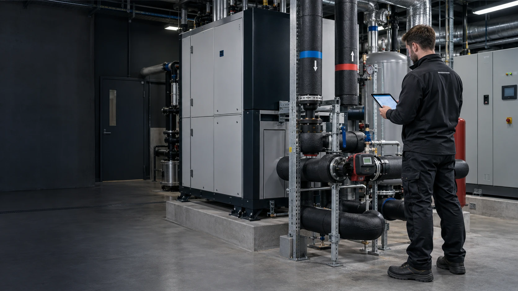
Heat pump performance monitoring
Read the heat meter over M-Bus, meter every electrical input, and compare COP over complete periods.
- Measure
- Delivered heat, heat-pump electricity, pump and auxiliary electricity, source and flow temperature
- Calculate
- Live COP from valid rate inputs; a seasonal performance factor only from complete matching energy totals across the defined season
- Sensors
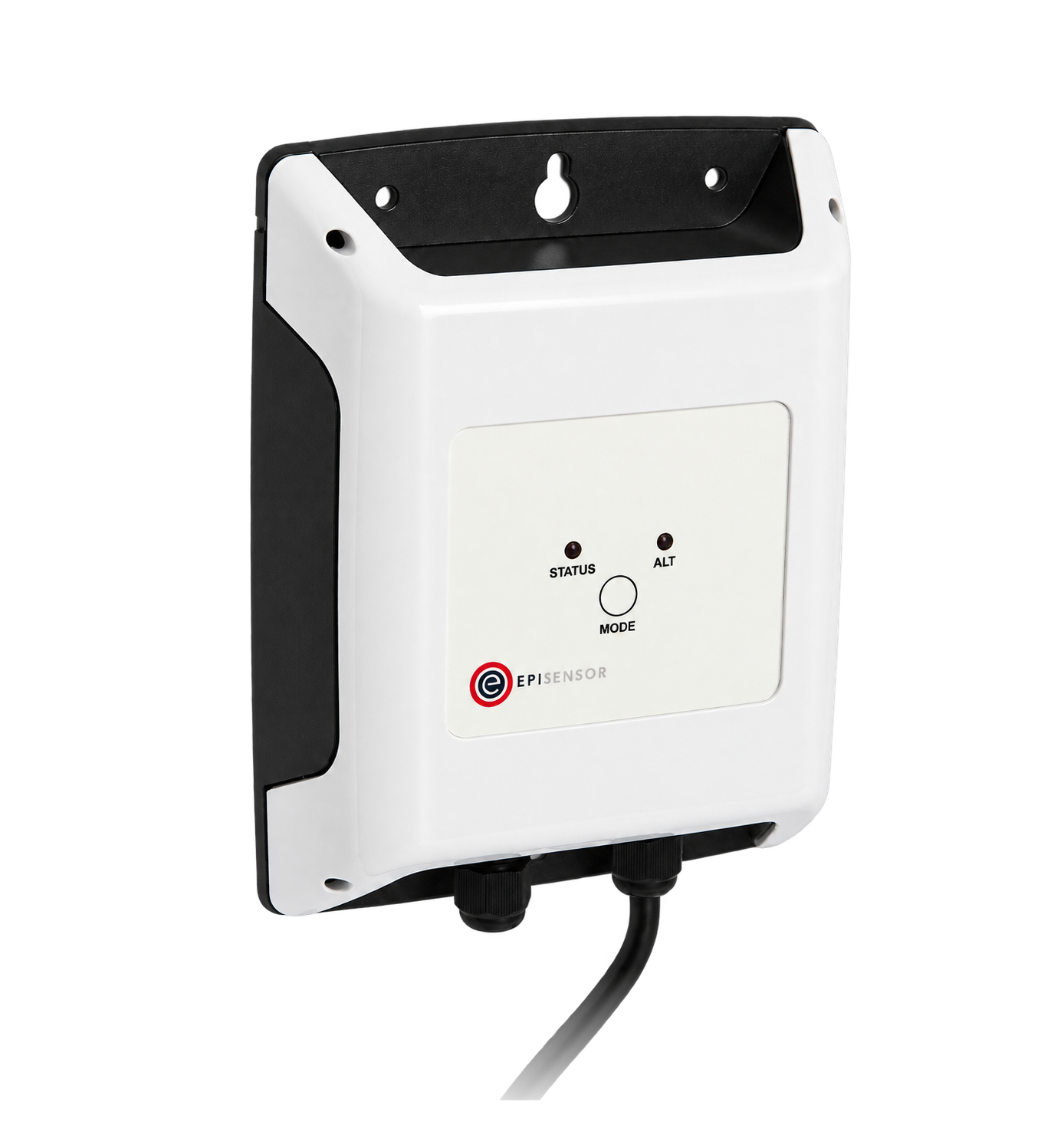
- ZHM-21, reads the heat meter's own energy record over wired M-Bus M-Bus Interface datasheet
- On site
- ZGW-20 Gateway, calculated sensors, with the inputs kept beside the result Gateway datasheet
Which electricity counts as input
A commercial heat pump monitoring plan begins with the boundary, not the formula. A heat pump on its own looks better than the system it sits in. Decide up front whether source pumps, load pumps, controls and any backup heater are inside the ratio, name that boundary beside every result, and measure every included input without overlap.
| Unit only | System | |
|---|---|---|
| Electrical input | The heat pump's own supply | Heat pump, circulating pumps, controls and backup heat |
| Answers | How the machine performs | What the heat actually costs to make |
| Watch for | A high figure that excludes the pumps | Auxiliary heat quietly carrying the load |
Hardware for a heat pump COP measurement
Use one interface for each compatible heat meter and one electricity meter per non-overlapping supply inside the declared boundary. Controller registers and an independent context-temperature point are optional: include them only where the available interface, register map and placement answer a defined operating question.
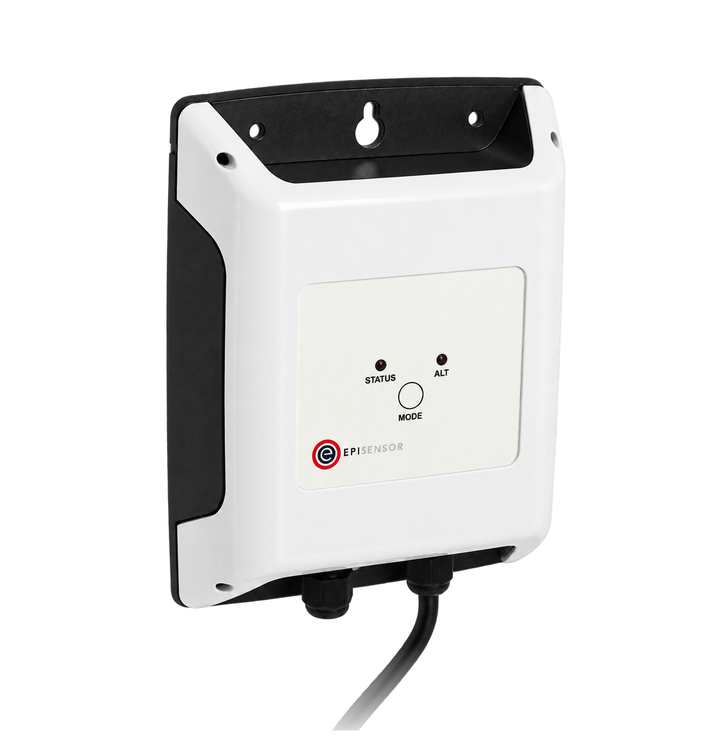
Reads the heat meter's delivered energy, volume and temperatures
1 per meter one connected meter each
2 m flying lead to the meter, 300 to 9,600 baud, up to 1,000 m of cable

The heat pump supply, and each pump or auxiliary heater inside the boundary
1 per supply three-phase, 3 or 4 wire
- Choose the CT rating per supply: 120 A split-core, or 300 A, 1 kA and 3 kA Rogowski coils

Keeps the heat, electricity and context records and evaluates configured live calculations in Edge
Start with 1 per plant area, then survey device count, wired routes and radio coverage commissioned on site
If the controller has a published register map

Operating mode, setpoint, defrost and compressor state from the heat-pump controller
1 per controller up to 30 registers
If there is no trustworthy source temperature already
Source or outdoor temperature, which is what the performance has to be read against
1 per point 2.5 m waterproof probe
 1 waterproof probe, 2.5 m lead
±0.2 °C from −20 to 70 °C, ±0.5 °C from −40 to 105 °C
Define the thermal and electrical boundary
Delivered thermal energy and every included electrical input need complete coverage over the same period. Rate-based COP also needs current rate values that refer to the same operating moment. If one input is estimated, stale or missing, the result inherits that limitation.
From the heat-pump boundary to a defensible result
Thermal output, electrical input and optional operating context follow distinct acquisition paths before Edge keeps the named records and evaluates configured calculations.
- M-Bus
- Zigbee
- Edge
- Platforms
| Position | What it tells you | Reference | Sensor |
|---|---|---|---|
| Delivered heat | The thermal energy delivered to the declared load-side circuit, or heat rate when the meter exposes one | Use the heat meter's own cumulative energy record for period totals; treat an exposed heat-rate register as a separate live value OMS | ZHM-21 (on this page) |
| Heat pump electricity | The input the machine drew, at its own supply | CT direction, ratio and phase assignment confirmed against a known operating condition | ZEM-65 (on this page), unit supply |
| Pumps and backup heat | The rest of the input, which is what separates the unit figure from the system figure | Every supply named in the boundary has its own meter | ZEM-65 (on this page), one per supply |
| Declared context temperature | One source, outdoor or store temperature against which performance can be compared | Record the exact probe position; this contextual point is not the heat meter's matched temperature pair Probe Temperature Sensor datasheet | TES-21 (on this page) |
| Mode and defrost | Optional context for whether a period was space heating, hot water or defrost | Only use controller registers where the model, firmware and register map are confirmed Modbus Interface datasheet | ZMB-31 (on this page) |
Meter the backup heater separately. An immersion or resistance heater on the same board makes the system figure fall without the heat pump changing. Meter it separately.
Keep defrost periods in. Excluding defrost periods flatters the result. Keep them in, and keep the state that says which they were.
Use the energy register for a period COP. A cumulative heat-energy register supports a period calculation. A heat-rate register supports a live COP only when the matching electrical power inputs are current and valid. Do not derive an instantaneous rate by silently differencing sparse cumulative totals.
Calculate COP and a measured-period performance factor
Live COP uses valid thermal and electrical rates for the same operating moment. A measured-period performance factor uses complete energy totals over exactly the same start and end times. Call that factor SPF only when the period and boundary genuinely represent the defined season.
COP = heat rate ÷ (heat-pump power + included auxiliary power)
PFperiod = delivered heat energy ÷ (heat-pump energy + included auxiliary energy)- heat rate
- live delivered thermal power from the heat meter, kW
- heat-pump power
- heat-pump electrical input, kW
- included auxiliary power
- included auxiliary input, kW
- delivered heat energy
- the heat meter's cumulative energy change over the complete period, kWh
- heat-pump and auxiliary energy
- electrical energy over the same period, kWh
Worked example
A week's heat-meter energy register rises by 1,240 kWh. The heat pump used 340 kWh and its included circulating pumps used 42 kWh over the same complete week. The measured-period factor is 1,240 ÷ 382 = 3.2. It is not yet a seasonal performance factor. Leaving the pumps out would give 3.6 for the same building and heat output, which is why the boundary belongs beside the number.
In Edge
A live Edge calculation can divide the current heat-rate input by the sum of the selected electrical-power inputs. Those inputs can carry different timestamps, so use a stale-input policy and inspect the result timestamp; a previous displayed result can remain after a suppressed evaluation. Treat zero or near-zero electrical input as an invalid denominator. Work period factors from complete aligned energy records, with register resets, restarts and missing coverage resolved before division.
Commissioning checks
Prove each input before the ratio is quoted to anyone.
-
The heat meter reads as it displays
Compare the energy, volume and temperatures in Edge with the meter's own display at the same moment.
Pass when every value and unit matches the display.
-
Every included supply is metered
Walk the boards and list each supply inside the boundary, then find its meter in Edge.
Pass when the list and the meters match, and anything left out is written down as excluded.
-
Any controller context is proved
If controller data is in scope, verify the exact model, firmware and register map, then observe the available space-heating, hot-water and defrost states against the plant.
Pass when each available state agrees with the plant, unknown codes stay unknown, and performance periods are not silently excluded.
-
A missing input withholds the answer
In an approved test environment, pause or simulate one heat or electricity input beyond the stale threshold, then inspect the result value and timestamp before and after recovery or restart.
Pass when the evaluation is suppressed or clearly invalid, no missing value becomes zero, and any previous displayed result is identifiable by its older timestamp.
-
Zero input cannot produce a believable COP
In an approved test environment, evaluate the calculation with zero or near-zero summed electrical input.
Pass when the denominator guard prevents a finite performance result and the condition is visible to the operator.
-
One period by hand
Take start and end heat and electricity totals for one complete period, check for resets and missing coverage, then divide the deltas on paper.
Pass when the hand figure matches the measured-period calculation for the same boundary and exact timestamps.
Limits of this measurement
A performance figure describes the period, the boundary and the weather it was measured in.
- An instantaneous COP is not a seasonal figure, and neither is a manufacturer's rating point.
- A week, day or partial heating season produces a measured-period factor, not automatically an SPF.
- A performance factor built on estimated heat output inherits the estimate's uncertainty, however precise the arithmetic looks.
- Comparing two seasons means comparing two weathers unless the source conditions are quoted with the figure.
- Monitoring approves nothing about the refrigerant, electrical, hydraulic or pressure design.
Sources
- OMS specification volume 2, primary communication (opens in a new tab) OMS Group
- Commission Decision 2013/114/EU, guidelines on calculating renewable energy from heat pumps (opens in a new tab) (opens in a new tab) European Commission
- M-Bus Interface datasheet (opens in a new tab) EpiSensor. Specifications, ranges and ordering codes.
Related
- OverviewEnergy monitoring
- CalculatorHeat meter check
- GuideEquipment performance monitoring boundaries
Third-party devices for this application
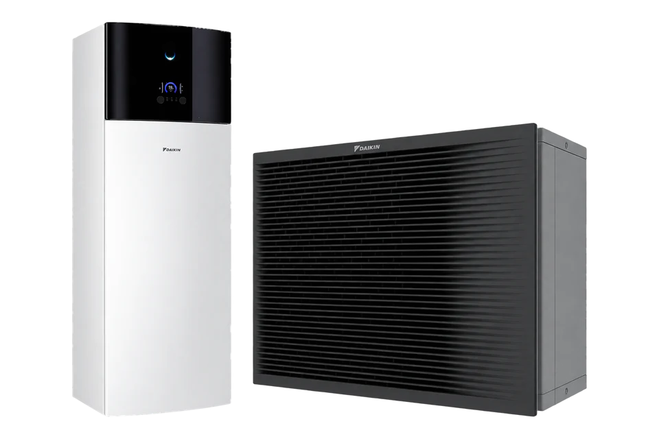
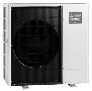
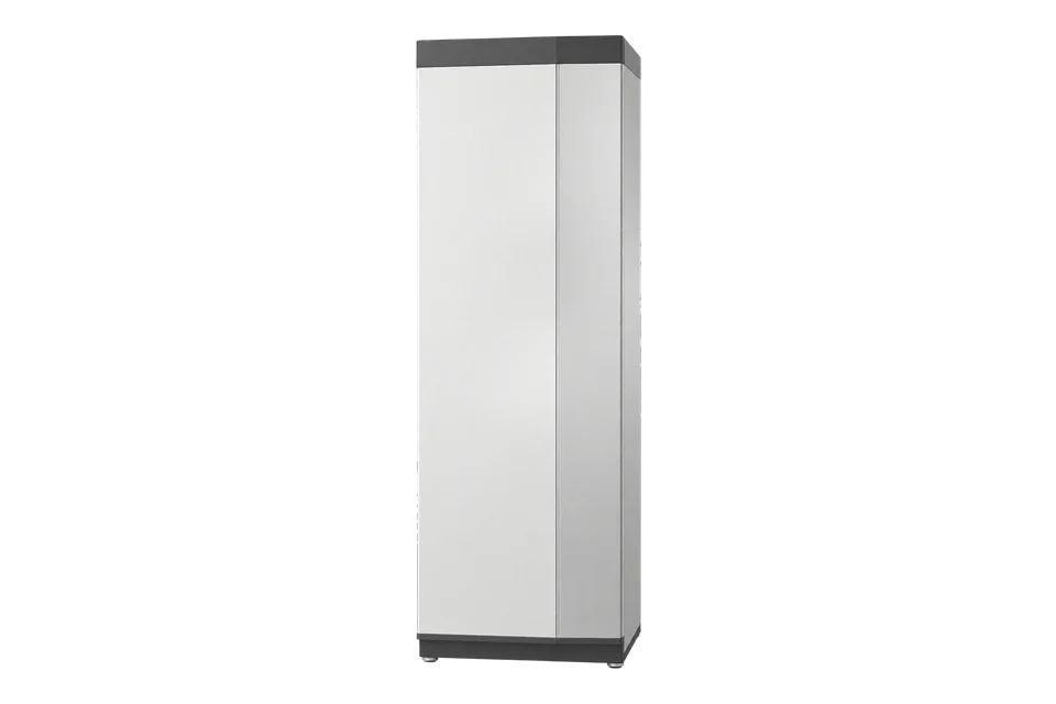
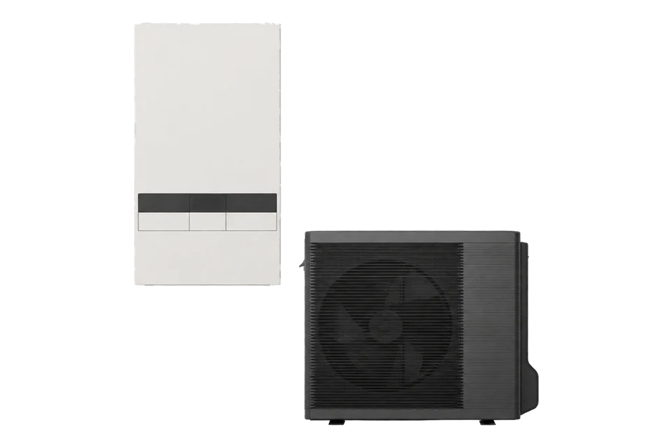
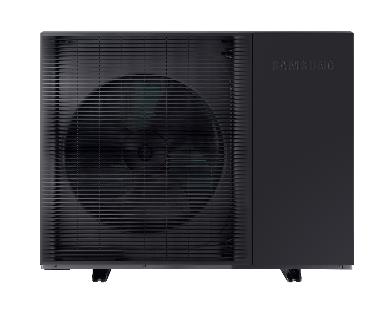
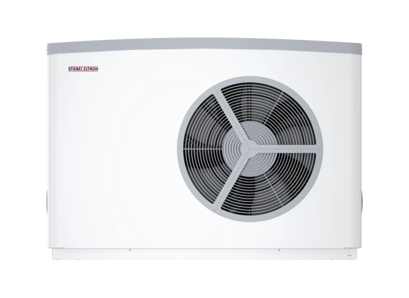
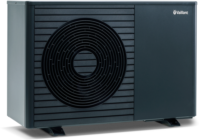
More in the Device Directory: Energy meters (62), Current transformers (7), Temperature and humidity sensors (21)
Settle which electricity counts before measuring SPF
An engineer can agree the boundary, check the meter can be read as it stands, and size the electricity meters.