Chiller performance monitoring
Cooling output from a flow reading and a matched entering-and-leaving temperature pair, divided by the metered electrical input.

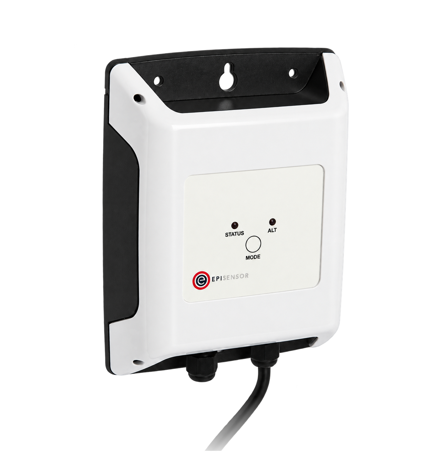

- Measure
- Chiller and pump electricity, chilled-water flow, entering and leaving water temperature
- Calculate
- Chiller COP and kW per ton, on the Gateway itself
- Sensors
- ZEM-65, Class 0.5S to IEC 62053-22, CTs calibrated with the meter Wireless 3-Phase Electricity Monitor datasheet
- On site
- ZGW-20 Gateway, calculated sensors and 1, 5, 15 or 30-second live stream Edge
Equipment COP or plant COP
Decide which electrical inputs belong inside the ratio before anything is installed. Both boundaries are valid, and they give different numbers for the same plant, so a comparison is only meaningful when both sides used the same one.
| Equipment COP | Plant COP | |
|---|---|---|
| Electrical input | The chiller only | Chiller, chilled-water and condenser-water pumps, tower fans |
| Answers | How the machine is performing | What the cooling actually costs |
| Meters | One at the chiller supply | One per pump or tower group as well |
Hardware for a chiller COP measurement
One meter per electrical input inside your boundary, one flow measurement, and the water temperatures from the chiller's own controller.
The chiller supply, and each pump or tower group inside the boundary
1 per supply three-phase, 3 or 4 wire
- Choose the CT rating for each supply: 120 A split-core, or 300 A, 1 kA and 3 kA Rogowski coils
Class 0.5S to IEC 62053-22 for the meter and its CTs together, 110 to 480 V line to line
The chilled-water flow transmitter's 4-20 mA output
1 per transmitter externally powered loop
0 to 20 mA at 0.001 mA resolution, up to 36 V DC, mains powered

Entering and leaving water temperature, setpoint and run state from the chiller controller
1 per controller up to 30 registers
Modbus RTU over RS-485, function codes 1 to 6, 15 and 16, cable runs to 1,000 m
Runs the COP calculation on site and keeps the inputs beside the result
1 per site up to 250 wireless devices
If the chilled-water circuit already has a heat meter
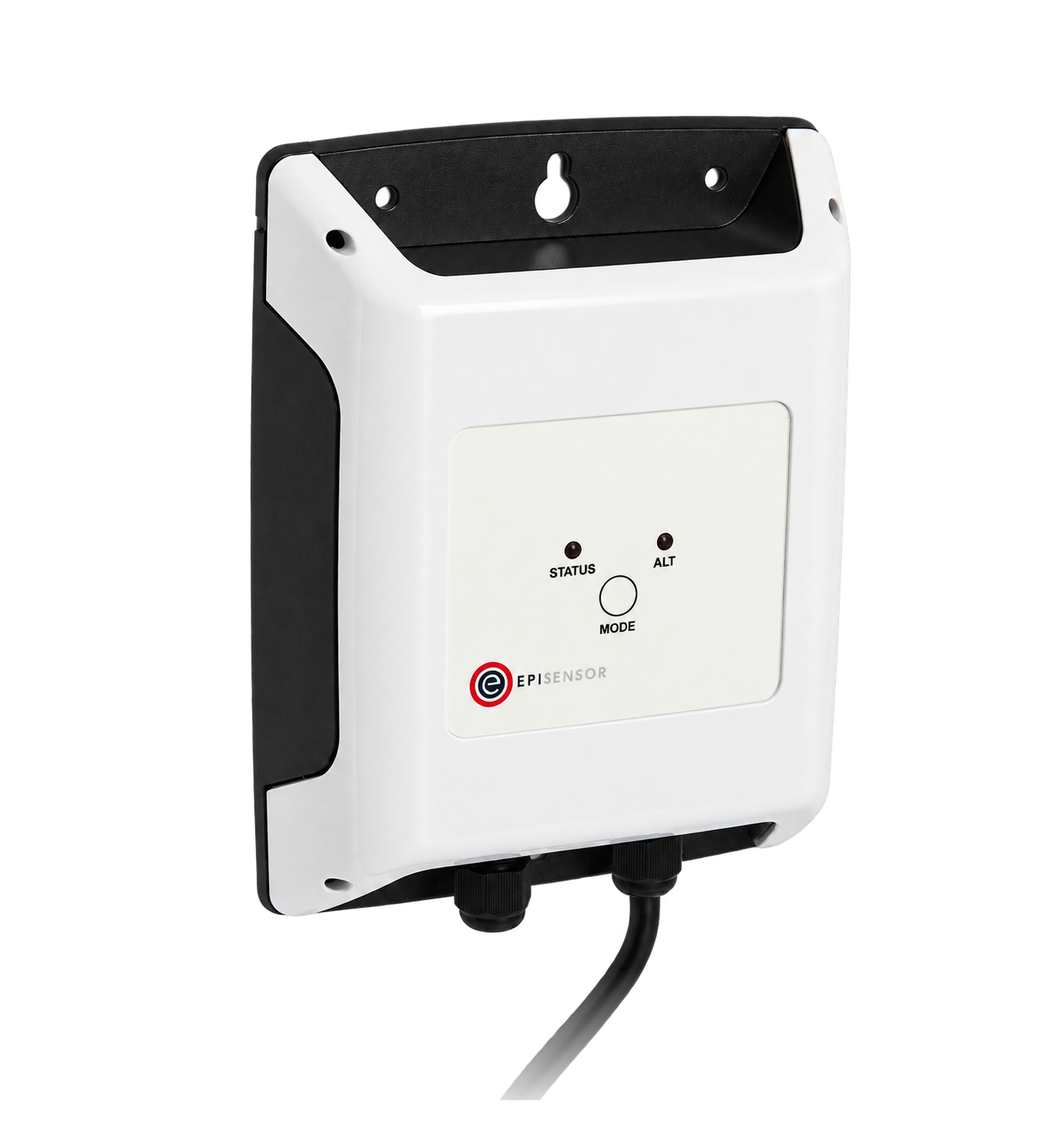
Reads the cooling energy from an existing wired M-Bus heat meter, instead of flow and temperatures
1 per meter one M-Bus meter each
What to measure on a chilled-water circuit
Four measurements make the ratio. Each one needs to be inside the same boundary and on the same clock as the others.
From field measurement to Edge
Each field signal reaches its named EpiSensor interface, reports through the site Gateway and is handled locally in Edge.
- Wired
- Zigbee
- Edge
- Platforms
| Position | What it tells you | Reference | Sensor |
|---|---|---|---|
| Chiller supply | The electrical input, and whether the machine is loaded or idling | Class 0.5S metering, CTs sized for the supply Wireless 3-Phase Electricity Monitor datasheet | ZEM-65 (on this page) |
| Pumps and tower fans | The rest of the plant input, when the boundary is plant COP | One meter per supply inside the boundary | ZEM-65 (on this page), one per group |
| Chilled-water flow | The volume flow the cooling calculation needs | Transmitter range, zero and units read from its own configuration Analogue Signal Sensor datasheet | ZIO-20 (on this page) |
| Entering and leaving water | The temperature difference across the evaporator | The chiller's own sensor pair, read over Modbus Modbus Interface datasheet | ZMB-31 (on this page) |
Do not read a small difference with surface probes. A 4 °C difference measured by two clamp-on probes carries more error than the result can stand. Use the chiller's matched pair, a heat meter, or immersion pockets.
Convert flow units once. Record whether the transmitter reports litres per second or cubic metres per hour, and convert once, in the calculation.
Use the glycol mix’s own heat capacity. A glycol mix has a lower specific heat capacity than water. Use the fluid's own values, from the supplier's data, at the operating temperature.
How to calculate chiller COP
Cooling output comes from flow and the matched entering-and-leaving water temperature pair. Divide it by the sum of every electrical input inside the chosen boundary, measured over the same interval.
Q = V × ρ × c × ΔT
COP = Q ÷ P
kW/ton = P ÷ (Q ÷ 3.5169)- Q
- cooling output, kW
- V
- volume flow, litres per second
- ρ
- fluid density, kg per litre
- c
- specific heat capacity, kJ per kg per K
- ΔT
- entering minus leaving water temperature, K
- P
- electrical input inside the boundary, kW
Worked example
Water at 12.0 °C entering and 7.0 °C leaving, flowing at 18.0 litres per second, gives Q = 18.0 × 1.0 × 4.18 × 5.0 = 376 kW. With the chiller drawing 96 kW, COP = 3.9 and kW per ton = 0.90. One refrigeration ton is 3.5169 kW of cooling.
In Edge
Build it as a calculated sensor on the Gateway. Use the Expression operation with the flow, the two temperatures and the power as explicit inputs, guard the division, and set the stale-input threshold so the result is suppressed rather than calculated from an old reading.
Commissioning checks
A ratio is only as good as its inputs, so check the inputs first and the ratio last.
-
Each meter is on the supply you think it is
Open and close one supply at a time, or step a known load, and watch which meter moves.
Pass when every meter is named for the supply that changed, and the phase order is confirmed by a competent person.
-
The flow signal is scaled
Compare the transmitter's own display or configuration with the value in Edge at two flows.
Pass when both values agree in the same units, and 4 mA reads as the transmitter's zero rather than as zero flow.
-
The temperature pair is trustworthy
Read entering and leaving temperature with the chiller off and the loop circulating.
Pass when the difference is close to zero, and any offset is recorded and applied consistently.
-
Cooling and power share one interval
Step the load or watch a stage change, and compare the timestamps of the flow, temperature and power readings.
Pass when the inputs move together, and none lags by more than the calculation's reporting interval.
-
One interval by hand
Take the raw values for a single interval and work the formula through on paper.
Pass when the hand calculation matches the Edge result, and any difference is explained by rounding.
Limits of this measurement
An instantaneous ratio describes one operating point, under the conditions it was measured in.
- It is not IPLV, NPLV, a seasonal figure or a certified rating-point result.
- Sensor error dominates when the temperature difference is small: a 0.2 °C error on a 4 °C difference is 5 per cent of the answer.
- A comparison between two periods means nothing unless the load, the entering condenser conditions and the boundary were the same.
- Monitoring does not establish refrigerant charge, mechanical condition or compliance with any code.
Sources
- Purchasing energy-efficient electric chillers (opens in a new tab) (opens in a new tab) US Department of Energy FEMP
- Wireless 3-Phase Electricity Monitor datasheet (opens in a new tab) EpiSensor. Specifications, ranges and ordering codes.
Related
-
Heat pump performance monitoring
Read the heat meter over M-Bus, meter every electrical input, and compare COP over complete periods. -
Boiler performance monitoring
A pulse counter on the fuel meter coming in, a heat meter on the way out, and the firing state that tells you which periods are worth comparing.
- OverviewEnergy monitoring
- CalculatorHeat meter check
- GuideEquipment performance monitoring boundaries
Third-party devices for this application



More in the Device Directory: Energy meters (62), Current transformers (7)
Agree the chiller boundary before anything is ordered
An engineer can agree the boundary, size the meters and the CTs, and write the calculation with you.