Wired M-Bus heat meter integration
One M-Bus interface per meter reads the meter's own energy, volume and temperature records over wired M-Bus, and Edge keeps them with their timestamps.

- Measure
- The heat meter's energy, volume, flow rate, flow and return temperature and status records
- Good practice
- Primary addresses 1 to 250, and 0 means unconfigured M-Bus
- Sensors
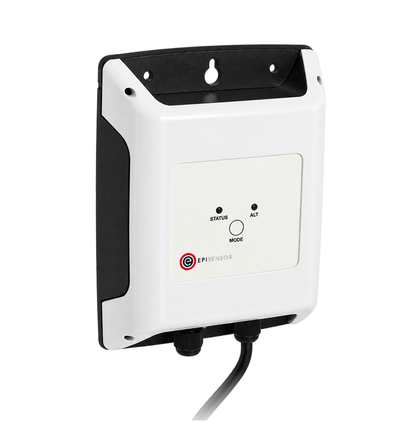
- ZHM-21, one M-Bus meter, 300 to 9,600 baud, up to 1,000 m of cable M-Bus Interface datasheet
- On site
- ZGW-20 Gateway, decoding, storage and onward integrations Gateway datasheet
Hardware for remote heat meter reading
The ZHM-21 is the M-Bus master for one meter, so a plant room with three heat meters takes three interfaces. An optional independent flow-and-return sanity check takes two pipe probes, one on each pipe.
Reads one wired M-Bus heat meter and sends its records over the wireless mesh
1 per meter one connected meter each
2 m flying lead to the meter, 300 to 9,600 baud, up to 1,000 m of M-Bus cable, mains powered
Decodes each meter's records, keeps them with their timestamps, and exports them
1 per site up to 250 wireless devices
If the meters have a Modbus module

Reads meters that offer Modbus RTU instead, several of them on one RS-485 bus
1 per bus up to 30 registers
If the meter's readings need an independent check
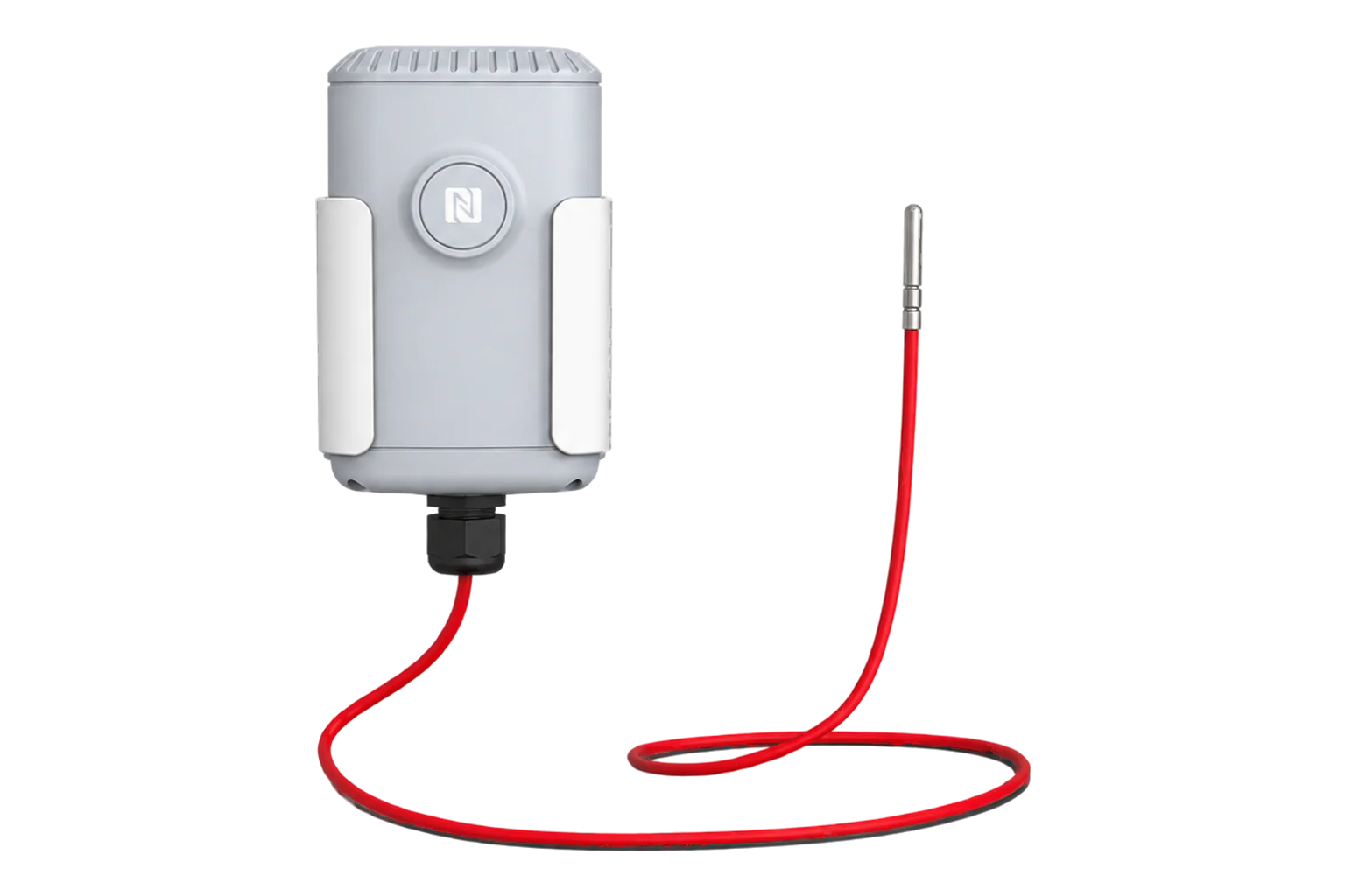
An independent pipe temperature beside the meter's own flow or return sensor
1 per pipe sanity check only
 1 steel pipe probe, 2 m lead
±0.2 °C from 0 to 70 °C, ±0.5 °C from −40 to 105 °C
Which heat meter records to read
Take the meter's own calculated records. They carry its approved calculator, its sensor pair and its units.
From field measurement to Edge
Each field signal reaches its named EpiSensor interface, reports through the site Gateway and is handled locally in Edge.
- M-Bus
- Zigbee
- Edge
- Platforms
| Position | What it tells you | Reference | Sensor |
|---|---|---|---|
| Energy total | The cumulative heating or cooling energy the meter has calculated | Read the meter's unit and tariff register, not a converted value OMS | ZHM-21 (on this page) |
| Volume and flow rate | Whether water is circulating at all, which separates no demand from a fault | Units and resolution from the meter's manual | ZHM-21 (on this page) |
| Flow and return temperature | The temperature difference the meter used, and its sign | The meter's declared sensor pair | ZHM-21 (on this page) |
| Status and error records | Whether the meter itself is reporting a problem with a sensor or its flow measurement | Model-specific: check which records the meter sends OMS | ZHM-21 (on this page) |
| Pipe temperature beside the meter | Whether the meter's sensors are installed where they claim to be | A check on the installation, never a replacement record | TES-21 (on this page) |
Use the relay for a valve only. The ZHM-21 has a Form C relay rated 1 A at 250 V AC, resistive, with 5,000 operations at full load. It is not intended for switching large electrical loads.
Check each meter model’s records. The interface reads meters from Kamstrup, Sontex, Itron, Sharky, Elster, Sensus and Landis+Gyr, and each model still decides which records it sends.
M-Bus meter settings that have to match
Every one of these lives in two places: the meter and the interface. A mismatch reads as a missing meter, not as an error.
| Setting | Typical value | Where to check |
|---|---|---|
| Primary address | 1 to 250, unique on the segment | The meter's display or its configuration tool. Address 0 means unconfigured, and 251 to 255 have reserved, selection and broadcast roles. |
| Baud rate | 2,400 baud | The meter's communication settings. The interface supports 300, 600, 1,200, 2,400, 4,800 and 9,600 baud. |
| Meters per interface | 1 | The ZHM-21 datasheet. A second meter needs a second interface. |
| Cable length | Up to 1,000 m | The ZHM-21 datasheet, then the far-end voltage and capacitance for the cable you actually have. |
| Unit loads per meter | 1 to 4 UL | The meter's datasheet. One unit load draws 1.5 mA in the idle state. |
| Records to read | Energy, volume, flow rate, flow and return temperature, status | The meter's manual: telegram support varies by model and configuration. |
| Reporting interval | 15 minutes | The sensor settings in Edge. Keep cumulative totals as totals; derive rates from them afterwards. |
Commissioning checks
The order matters here: the reading is only evidence once the meter's own display has been recorded.
-
Record the meter before touching it
Photograph the display, and write down the serial number, the address, the units and the energy total with the time.
Pass when the record names one meter and one circuit, and can be read months later.
-
Connect and read once
Wire the interface's M-Bus lead to the meter, power it, and read the meter through the Gateway.
Pass when the meter answers on its own address, with no retries needed.
-
Compare every record with the display
Put the energy, volume, flow rate and temperatures beside the meter's display at the same moment.
Pass when every value and unit matches the display, including the decimal place.
-
Break the connection deliberately
Disconnect the meter's M-Bus lead for longer than the reporting interval.
Pass when Edge shows no new reading rather than repeating the last one, and any alarm names the meter.
-
Reconcile a bounded period
Read the display again after a day and compare the difference with the readings recorded over the same period.
Pass when the two agree within the meter's own resolution, and any rollover is written down.
Limits of this measurement
Reading a meter is not the same as approving it.
- M-Bus access does not certify the meter, its sensor pair, its installation or its suitability for billing.
- A shared protocol is not a shared record map: two meters of the same make can send different records.
- Energy worked out from flow and temperatures is a sanity check on the meter, not a substitute for its calculator.
- One interface reads one meter. An existing multi-meter segment needs its own unit-load, capacitance and topology design.
Sources
- OMS specification volume 2, primary communication (opens in a new tab) OMS Group
- M-Bus data link layer (opens in a new tab) (opens in a new tab) M-Bus Usergroup
- Technical report 02, wired M-Bus (opens in a new tab) OMS Group
- M-Bus Interface datasheet (opens in a new tab) EpiSensor. Specifications, ranges and ordering codes.
Related
-
Heat pump performance monitoring
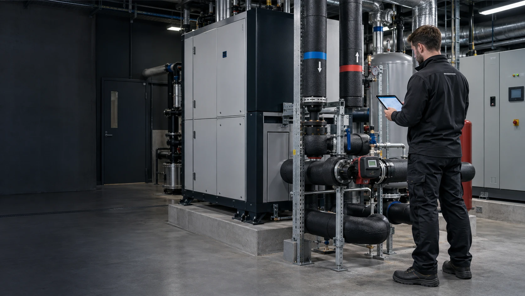
Read the heat meter over M-Bus, meter every electrical input, and compare COP over complete periods. -
Pulse meter remote monitoring
A counter on the meter's existing pulse output, the pulse weight recorded once, and a totaliser reading that lets you prove the counts later.


Third-party devices for this application
More in the Device Directory: Temperature and humidity sensors (21)
Check which heat meters can be read as they stand
An engineer can check the models and their records, count the interfaces, and tell you what has to be set on each meter.