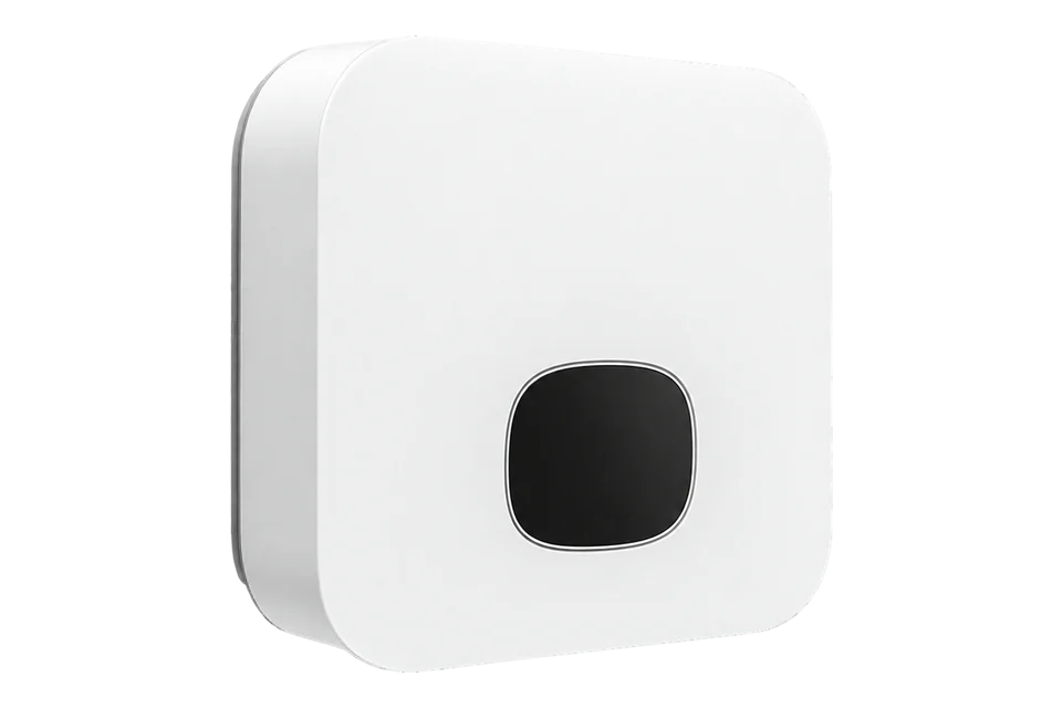
Growatt MIN 2.5-6KTL-XH2
Single-phase battery-ready PV inverter
Growatt VPP V2.03 explicitly lists MIN 2500-6000TL-XH2 in Annex 3-1 with equipment type 5100. It provides read-only identity, signed active power and grid frequency registers. Combine this public starting map with the exact-family port roles below and a local value comparison. Direct Edge installation remains untested.
- RS485
- Modbus RTU
Single-phase battery-ready PV inverter
Compatibility
Monitoring and VPP port roles documented; protocol unverified
The exact-family manual defines physical port roles; Growatt-authored VPP V2.03 defines Modbus RTU identity and telemetry for this model family. The actual endpoint and a local comparison remain installation tasks.
MIN 2500TL-XH2 through MIN 6000TL-XH2 in the RJ45 manual only. Capture the exact rating, firmware, country grid code, battery, meter, logger and port occupancy. The earlier MIN-XH, MIN-XH2 US and MOD/MID XH families have different electrical and interface scopes.
Models
| Models | Interface | Route into Edge |
|---|---|---|
| MIN 2500/3000/3600/4200TL-XH2 | SYN third-party monitoring RS485A2/B2; separate RS485 VPP pair A3/B3 | The manual lists 2.5, 3, 3.6 and 4.2 kW AC ratings. Obtain the installed firmware's approved read protocol before planning an Edge client. |
| MIN 4600/5000/6000TL-XH2 | The same labelled RJ45 roles, with a separate commissioned meter and optional battery | The manual lists 4.6, 5 and 6 kW AC ratings. Confirm the meter, battery and local grid-code limits before a flexibility design. |
Specifications
Growatt's RJ45 manual names seven MIN-XH2 ratings from 2.5 through 6 kW, a single-phase 230 V grid connection, two MPPTs with one PV string each, 16 A maximum input per tracker and an IP66 enclosure. The July 2026 family datasheet and product page corroborate the battery-ready and dual-MPPT positioning. Battery readiness does not mean an installed battery or backup system.123
- Exact family
- MIN 2500, 3000, 3600, 4200, 4600, 5000 and 6000TL-XH21
- Rated AC output
- 2.5, 3, 3.6, 4.2, 4.6, 5 and 6 kW respectively; single phase, nominal 230 V1
- PV inputs
- Two MPPTs, one string per tracker, 16 A maximum input and 24 A maximum short-circuit current per tracker13
- SYN monitoring pair
- RJ45 pins 3/6: RS485A2/B2 for Min ShineBus, third-party monitoring equipment or Backup Box1
- VPP-labelled pair
- RS485 RJ45 pins 1/2: RS485A3/B3; VPP protocol communication label, command contract not supplied1
- Meter pair
- Meter RJ45 pins 5/4: RS485A1/B1 for the commissioned energy meter1
- CT input
- COM or RS485 RJ45 pins 4/5; manual notes a 100 A/40 mA CT ratio1
- Enclosure
- 375 × 350 × 160 mm, 10.8 kg, IP661
Interface
Documented measurements and integration boundaries for MIN 2.5-6KTL-XH2.
- FC03 holding 30000: equipment type 5100; holding 30099: protocol version. FC04 input 31100/31101: signed active power at 0.1 W; input 31105: grid frequency at 0.01 Hz. Input 31000 supplies working state and 31005/31007 fault/alarm codes.
- RS485 RJ45 pins 1/2 are RS485A3/B3, explicitly labelled for VPP protocol communication. Growatt VPP V2.03 lists MIN-XH2 and provides the read map used below; the SYN monitoring pair is a separate port.
- Meter RJ45 pins 4/5 are RS485B1/A1 for the energy meter. The manual's CT connections are on COM or RS485 pins 4/5, with a 100 A/40 mA CT ratio note. They are not spare telemetry or VPP inputs.
- The battery communication port and the USB-A ShineWiLan-X2/ShineLink-X2/Shine4G-X logger path are distinct. A logger's LAN connection does not establish a local inverter Modbus TCP server or open data API.
- The European DRMS RJ45 function is described as a Power Control Interface with a 5 V input limit. It is a commissioned power-control function, not a generic software write channel. Preserve regional protection and export settings.
Assessment
MIN 2500-6000TL-XH2 with exact-family wiring and Growatt VPP V2.03 monitoring reads. Installed-site and native Edge acceptance have not been performed.
- InteroperabilityLimited
- The public VPP map names this family and documents Modbus RTU register functions, signed data types and scales; the actual shared-port topology remains site-specific.14
- AccuracyLimited
- VPP V2.03 defines active power, frequency, operating state and meter values with types and units. Compare inverter and grid-meter readings separately; site accuracy and freshness have not been measured.14
- SecurityNot yet assessed
- No third-party serial authentication, authorization or transport-security terms are established.1
- ReliabilityNot yet assessed
- No independent-client polling availability, reconnect behavior or historical backfill guarantee is established.13
- RuggednessSupported with conditions
- The manual specifies an IP66 enclosure and operating limits; site installation and derating still determine suitability.1
- ScalabilityNot yet assessed
- The RJ45 labels do not specify how many independent clients or aggregated inverters the installed endpoint supports.1
Setup
-
Trace the monitoring and VPP ports
Trace the six labelled RJ45 ports physically. SYN pins 3/6 are the documented third-party monitoring pair; RS485 pins 1/2 carry the VPP protocol label. Keep the meter, battery and CT wiring in their commissioned roles.
-
Read identity, power and frequency
Growatt VPP V2.03 (1 September 2025), Tables 2.1/2.2 and Annex 3-1, is the best-effort starting map. Use the installed serial address and baud rate with 8N1. FC03 holding address 30000 identifies the equipment type; 30099 identifies the protocol version (203 means V2.03). These are wire addresses: add one only if your client uses one-based register numbers. Read power with FC04 input address 31100, two words: PDU 04 79 7C 00 02, excluding slave address and CRC. Decode high-word-first signed INT32 and multiply by 0.1 W. Synthetic bytes 00 01 E2 40 give 12345.6 W; FF FF FF 9C give -10 W. The map defines positive active power as export and negative as import. Read frequency at input address 31105 as UINT16 × 0.01 Hz: 13 88 gives 50 Hz. Compare with simultaneous local monitoring before using the values.
-
Preserve the commissioned system
Use the commissioned inverter or logger endpoint. The protocol says VPP authority register 30100 must be enabled; have the installer confirm its existing configuration without exploratory writes. Keep occupied meter, battery, parallel and backup buses intact. This procedure supplies monitoring reads, not an Edge-tested import or permission to dispatch.
-
Check the VPP endpoint configuration
Use the commissioned inverter or logger endpoint. The protocol says VPP authority register 30100 must be enabled; have the installer confirm its existing configuration without exploratory writes. Keep occupied meter, battery, parallel and backup buses intact. This procedure supplies monitoring reads, not an Edge-tested import or permission to dispatch.
Common questions
- Can Edge read a MIN-XH2 directly from the SYN port?
- The published VPP map supplies a useful Modbus RTU starting point for this exact family. Use the visible read procedure and a commissioned endpoint; keep the separate meter, battery and backup pairs in their assigned roles. No Edge field-test result is claimed.14
- Does the VPP-labelled RS485 port make this inverter dispatch-ready?
- Growatt VPP V2.03 now supplies a public data and command specification for this family. The read procedure below uses identity and telemetry only. Dispatch still requires the commissioned authority, constraints and control design; this guide does not authorize control writes.14
Related devices
Sources
- MIN 2500-6000TL-XH2 installation and operation manual, RJ45 edition, GR-UM-290-A-02 (opens in a new tab) (PDF)
- MIN 2500-6000TL-XH2 datasheet, July 2026 (opens in a new tab) (PDF)
- MIN 2500-6000TL-XH2 product page (opens in a new tab)
- Growatt VPP communication protocol V2.03 (1 September 2025; public repository mirror) (opens in a new tab) (PDF)
Further reading
Product names and trademarks belong to their owners. Publication does not imply endorsement or a commercial relationship.