Sungrow SG15/17/20RT-P2
Three-phase PV string inverter
The SG15RT-P2, SG17RT-P2 and SG20RT-P2 share Sungrow's two-MPPT three-phase design. The Ver16 manual assigns COM2 A1/B1 to external RS-485 communication and A2/B2 to the export-control meter. It prohibits simultaneous A1/B1 daisy-chain use with the COM1 WiNet module. No exact-family, firmware-matched third-party register map is established here, so a direct Edge monitoring or control path remains unverified.
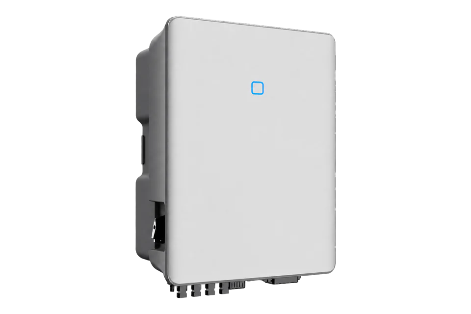
- RS485
Three-phase PV string inverter
Compatibility
Independent monitoring needs an exact register contract
The Sungrow Ver16 manual documents COM2 A1/B1 RS-485 communication to an external device and a daisy chain, but the retained manual and datasheet do not provide an SG15/17/20RT-P2 firmware-matched register map, read permissions or an Edge import. WiNet Ethernet does not establish a native Modbus TCP server.
SG15RT-P2, SG17RT-P2 and SG20RT-P2 only. Confirm the full nameplate, firmware, regional grid code, fitted WiNet module, logger and meter. COM2 A1/B1 cannot be used simultaneously with the documented COM1 WiNet setup. Older RT models without -P2 and SG15/20/25CX-P2 are different products.
Models
| Models | Interface | Route into Edge |
|---|---|---|
| SG15RT-P2, SG17RT-P2 and SG20RT-P2 | COM2 RS485-1 A1/B1 for external-device or inverter daisy-chain communication; meter A2/B2 is a different pair | Identify the existing COM1 WiNet and logger arrangement before considering any independent serial client. Obtain a matching inverter or logger read protocol first. |
| SG3.0-20RT without -P2 | The shared Ver16 manual covers these older RT models too, but distinguishes their WiNet-S2 accessory from the P2 WiNet-S arrangement | Do not infer that connector or firmware assumptions from the non-P2 models apply to an installed P2 unit. |
Specifications
The exact-family V2 datasheet names SG15RT-P2, SG17RT-P2 and SG20RT-P2 with 15, 17 and 20 kW rated AC output, two MPPTs, two strings per MPPT and 22 kg enclosure weight. The newer Ver16 manual is the source for regional apparent-power limits and the COM connector roles. A shared housing does not make non-P2 or CX-P2 guides interchangeable.12
- PV inputs
- Two MPPTs; two strings per MPPT; 1100 V maximum PV input2
- PV input current
- 64 A total, 32 A per MPPT; 80 A maximum short-circuit current total2
- Regional AC maximum
- 15/17/20 kVA for AU, BE and DE; 16.5/18.7/22 kVA for other manual configurations1
- COM2 monitoring pair
- RS485-1 A1/B1 for inverter daisy chain or external device; not simultaneous with COM1 WiNet1
- COM2 meter pair
- A2/B2 for feed-in power meter; A3/B3 reserved1
- RS-485 chain boundary
- No more than five inverters at one point of connection; shielded twisted pair, up to 10 m between devices1
- Enclosure
- 370 × 480 × 195 mm, 22 kg, IP652
Interface
Documented measurements and integration boundaries for SG15/17/20RT-P2.
- COM2 A1/B1 is the documented RS-485 daisy-chain pair. The manual limits a chain at one point of connection to five inverters and specifies shielded twisted pair with no more than 10 m between devices; a logger's own limits still need checking.
- COM2 A2/B2 is assigned to the feed-in power meter and A3/B3 is reserved. The meter detects current direction and magnitude; Sungrow says its data may not be used for billing. Neither pair is a spare third-party telemetry port.
- The manufacturer describes 24/7 online monitoring and an integrated display, but these do not establish an external register address, scale, update interval or native inverter Ethernet service.
- Regional AC apparent-power limits differ. The Ver16 manual gives 15/17/20 kVA maximum for AU, BE and DE, versus 16.5/18.7/22 kVA in other listed configurations. Verify the nameplate and grid setting before sizing or comparing output.
- DRM and emergency-stop terminals are control and safety functions. This guide does not authorize inverter write commands, export-limit changes or demand-response actuation.
Assessment
SG15RT-P2, SG17RT-P2 and SG20RT-P2, Ver16 manual and V2 datasheet. No firmware-matched external read map, Edge integration or control acceptance is claimed.
- InteroperabilityLimited
- An external-device RS-485 pair is documented, but WiNet coexistence is restricted and no exact-family third-party read map is retained.1
- AccuracyLimited
- Display and online monitoring exist, yet independent register scaling, freshness and grid-meter provenance are not established by these sources.12
- SecurityNot yet assessed
- The manual describes communication wiring but does not establish authentication or encryption for an independent RS-485 client.1
- ReliabilityNot yet assessed
- Online monitoring is advertised, but no third-party polling availability or historical backfill guarantee is established.12
- RuggednessSupported with conditions
- The datasheet specifies IP65, C5 anti-corrosion and the ambient range. Suitability still depends on the exact site installation and regional derating.12
- ScalabilityLimited
- The manual permits at most five daisy-chained inverters at one point of connection and 10 m between devices; an external polling capacity is not documented.1
Setup
-
Read the complete installed nameplate and firmware.
Confirm SG15RT-P2, SG17RT-P2 or SG20RT-P2, the country setting, existing meter, COM1 WiNet module and any logger before choosing a telemetry path.
-
Trace COM2 wiring: A1/B1 is the inverter communication pair, A2/B2 belongs to the feed-in meter and A3/B3 is reserved.
Do not move the meter or use the reserved pair for a monitoring client.
-
If COM1 WiNet is fitted, preserve the manufacturer's exclusion of simultaneous WiNet and A1/B1 daisy-chain communication.
Agree any change with the plant owner and Sungrow installer before altering network or serial wiring.
-
Request the manufacturer-approved protocol for the installed inverter or logger and firmware: function codes, read permissions, address base, widths, word order, scaling, exception values and polling interval.
The retained sources do not establish these items.
-
Only after that contract and bus ownership are confirmed should an installer perform a bounded read and compare it with the inverter display and an independently identified grid meter.
Document timestamps, stale-data behaviour and the actual measurement boundary.
-
Keep grid-code, export-limit, power-factor, DRM, emergency-stop, start/stop and firmware operations under the authorized plant controls.
A VPP dispatch route needs a separate control and acceptance design.
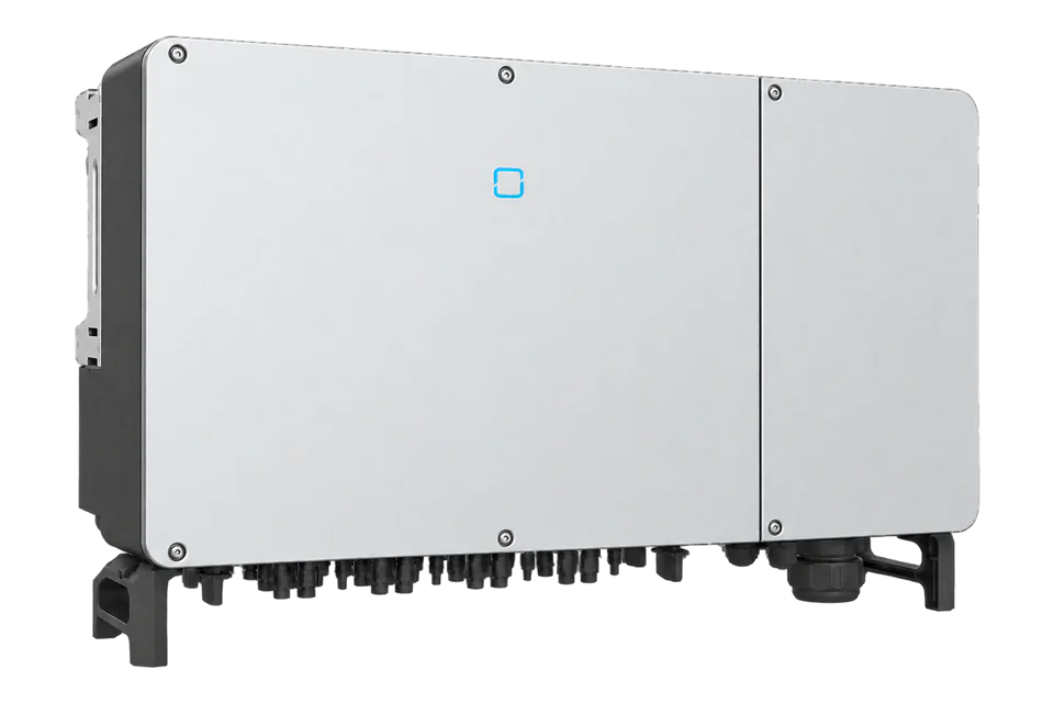
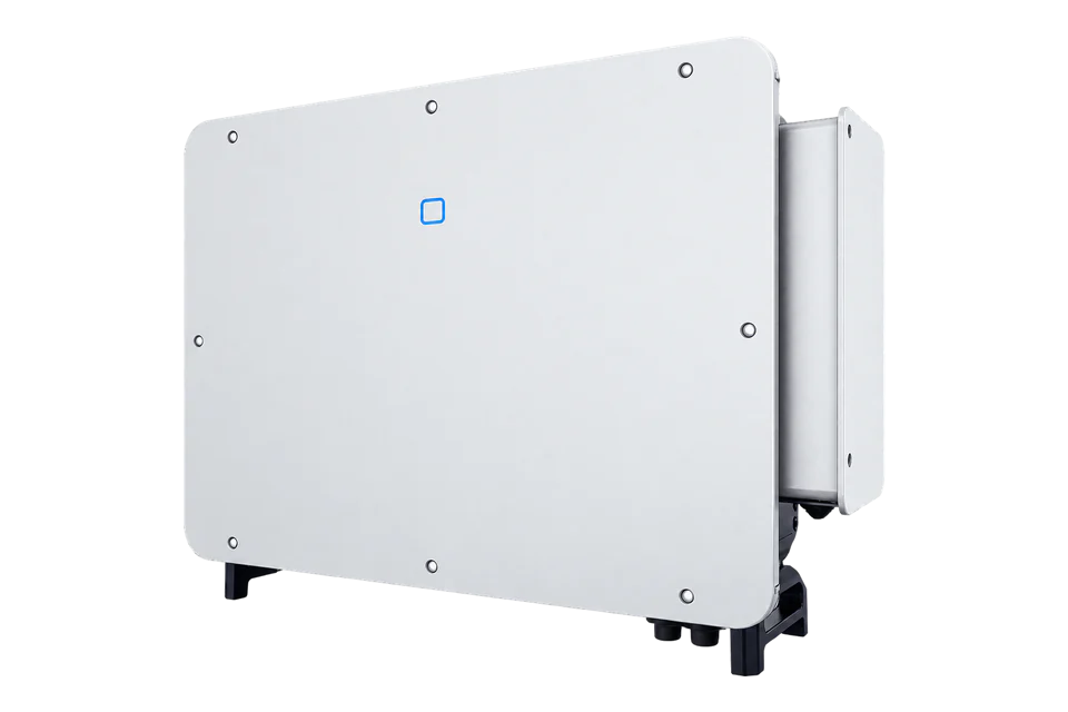
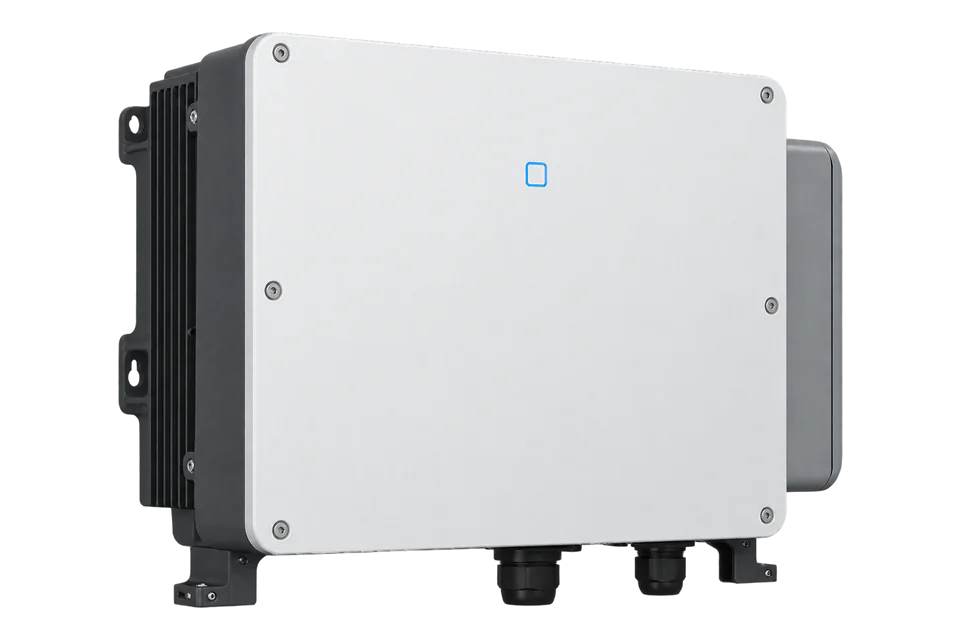
Related devices
Sources
- SG3.0-20RT and SG5.0-20RT-P2 user manual, Ver16, October 2025 (opens in a new tab) (PDF)
- SG15/17/20RT-P2 datasheet, V2 (opens in a new tab) (PDF)
- SG15/17/20RT-P2 official product page (opens in a new tab)
Further reading
Product names and trademarks belong to their owners. Publication does not imply endorsement or a commercial relationship.