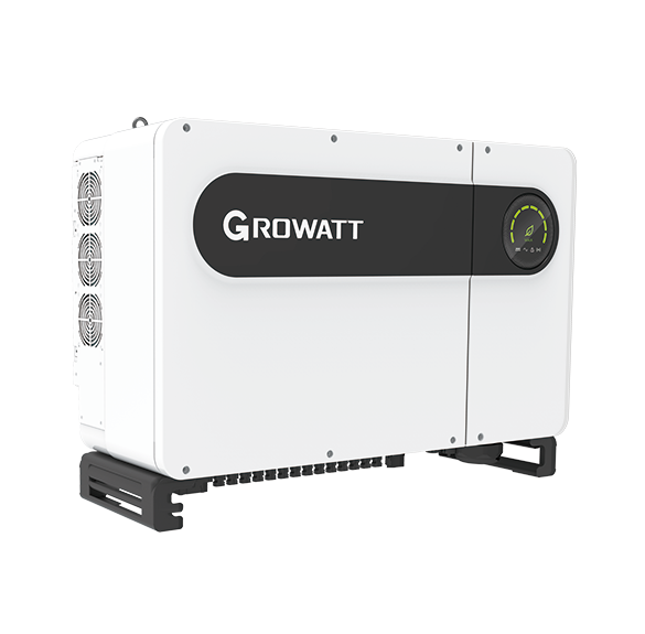
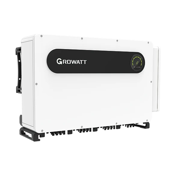
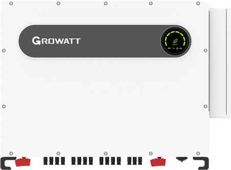
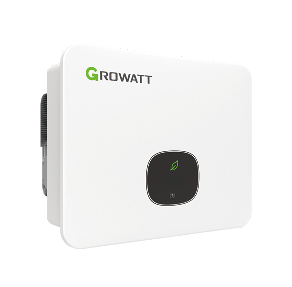
Growatt MAX 100-150KTL3-X2
Commercial PV inverter
Monitor MAX 100–150KTL3-X2 production through its RS485 inverter bus. Growatt’s V1.24 MAX-family map provides best-effort state, AC power and frequency reads, with a local display comparison before adding more points.
- RS485
- PLC
- Modbus RTU
Commercial PV inverter
Compatibility
Direct Edge integration not yet verified
Growatt’s manufacturer-authored V1.24 map names MAX/TL3-X and defines first-group state, power and frequency registers. It does not enumerate every newer suffix. Use this starting revision with the installed serial settings and compare readings with the local display.
MAX 100-125KTL3-X2 LV or MAX 124-150KTL3-X2 MV only. Record the full model, grid variant, firmware and communication accessory before requesting the matching interface specification.
Models
| Models | Interface | Route into Edge |
|---|---|---|
| MAX 100/110/120/125KTL3-X2 LV | 380 or 400 V class; eight MPPTs | Do not apply the 480 V MV electrical limits. |
| MAX 124/125/136/150KTL3-X2 MV | 480 V class; eight MPPTs | Record the exact rating and regional grid code. |
Specifications
The LV and MV groups use different AC voltage classes. The nameplate rating and suffix must be captured before applying electrical or monitoring assumptions.123
Interface
Documented measurements and integration boundaries for MAX 100-150KTL3-X2.
- V1.24 first-group input 0 gives operating state, 35/36 give AC output power at 0.1 W per count, and 37 gives frequency at 0.01 Hz. These are inverter production measurements, separate from the site import/export meter.
- Every value must retain its source device and measurement boundary; inverter, meter, logger and controller values are not interchangeable.
- No export-control, power-command, battery, generator, protection or grid-setting write is approved by this guide.
Assessment
MAX 100-125KTL3-X2 LV or MAX 124-150KTL3-X2 MV only. Record the full model, grid variant, firmware and communication accessory before requesting the matching interface specification.
- InteroperabilityLimited
- The X2 manual documents the inverter monitoring bus, and Growatt V1.24 provides a MAX-family Modbus RTU starting map. Confirm the commissioned bus role and compare the first decoded readings locally.1234
- AccuracyNot yet assessed
- The MAX-family map defines AC power and frequency types and scaling. Compare the first readings with the inverter display and check freshness on the installed unit.1234
- SecurityNot yet assessed
- The retained sources do not establish authentication, encryption or read-only privilege separation for a third-party client.123
- ReliabilityLimited
- Electrical and environmental limits are published, while communication recovery, stale data and concurrent-client behavior remain unverified.123
- RuggednessSupported with conditions
- The manufacturer publishes enclosure and operating limits; the installation must still meet those limits.123
Setup
-
Record the complete identity
Photograph the nameplate and record the exact model, serial number, installed firmware and communication accessories. Do not select a point map from the family name alone.
-
Map the commissioned topology
Identify the installed logger and RS485 terminal type. The X2 manual gives RS485-1 IN on pins 3 A1/4 B1, OUT on 5 A1/6 B1, and shielding on 1/2. Preserve existing logger and export-control roles; do not add a second polling client to the same bus.
-
Read state, power and frequency
Use the commissioned inverter address with one polling client. V1.24 specifies 8N1, default 9600 baud and at least 850 ms between commands, recommending 1 s. The X2 manual describes 38400 baud: use the installed settings. FC04 input 0 reads state: 0 waiting, 1 normal, 3 fault. FC04 wire 35, quantity 3, uses PDU 04 00 23 00 03. Join registers 35/36 high word first as an unsigned integer and multiply by 0.1 W; register 37 is frequency × 0.01 Hz. Synthetic bytes 00 01 E2 40 13 88 give 12345.6 W and 50 Hz. Addresses are zero-based wire offsets; the PDU omits address and CRC. Compare with the local display before extending this MAX-family starting map.
-
Keep control outside this guide
Do not propose active-power, reactive-power, export-limit, battery, generator, protection or grid-setting writes. Those functions need a separate engineered control and safety case.
Common questions
- Does a published RS485 or Ethernet interface prove direct Edge compatibility?
- The X2 manual establishes the monitoring wiring. Growatt V1.24 supplies a MAX-family Modbus RTU starting map: the setup procedure gives state, power and frequency reads. Use one client and compare locally; a ready-made Edge import is separate.1234
Related devices
Sources
- MAX 100-150KTL3-X2 LV/MV user manual (opens in a new tab) (PDF)
- MAX 100-125KTL3-X2 LV datasheet (opens in a new tab) (PDF)
- MAX 124-150KTL3-X2 MV datasheet (opens in a new tab) (PDF)
- Growatt Inverter Modbus RTU Protocol V1.24 (AMOS public mirror) (opens in a new tab) (PDF)
Further reading
Product names and trademarks belong to their owners. Publication does not imply endorsement or a commercial relationship.