Growatt MID 11-30KTL3-XH
Commercial battery-ready PV inverter
The MID 11-30KTL3-XH combines PV conversion with optional APX battery storage. Growatt documents the COM connector, parallel operation and its own monitoring accessories. The available exact-family sources do not supply a firmware-matched third-party inverter register map, so direct Edge monitoring and control remain unverified.
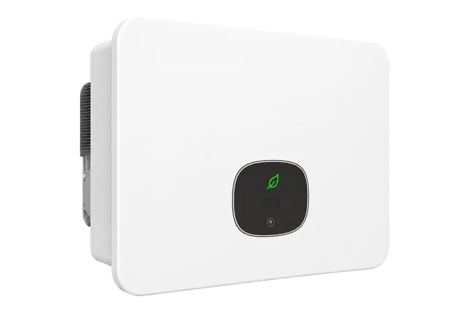
- RS485
Commercial battery-ready PV inverter
Compatibility
Direct Edge integration not yet verified
The May 2024 manual assigns distinct RS-485 pairs to parallel, meter, battery and SYN communication. Its Modbus RTU meter specifications do not establish an inverter register map or a third-party client interface.
MID 11, 12, 13, 15, 17, 20, 25 and 30KTL3-XH only. Match the complete nameplate, firmware, regional configuration and installed accessories to the applicable manual. MID TL3-X/X2 and MID 8-15KTL3-XH (L) require separate documentation.
Models
| Models | Interface | Route into Edge |
|---|---|---|
| MID 11, 12, 13, 15, 17 and 20KTL3-XH | Two MPPTs; 30-pin COM roles defined in the May 2024 manual | Identify the exact rating and installed firmware before requesting an inverter or logger telemetry specification. |
| MID 25 and 30KTL3-XH | Three MPPTs; separate meter, battery, parallel and SYN connections | The shared family connector does not establish shared third-party registers across firmware revisions. |
Specifications
The family covers eight three-phase ratings from 11 to 30 kW. The 11 to 20 kW models have two MPPTs and the 25 and 30 kW models have three. The current datasheet describes two high-voltage battery ports and APX battery options. Confirm battery compatibility and backup equipment against the installed revision before extending a PV system.2
- Models
- MID 11, 12, 13, 15, 17, 20, 25 and 30KTL3-XH2
- Rated AC power
- 11, 12, 13, 15, 17, 20, 25 and 30 kW respectively2
- MPPTs
- Two on 11 to 20 kW models; three on 25 and 30 kW models2
- Parallel communication
- COM pins 3/4: RS485A1/B11
- Meter communication
- COM pins 5/6: RS485A3/B31
- Battery communication
- Battery 1 pins 7/8; Battery 2 pins 27/28: RS485A2/B21
- SYN communication
- COM pins 23/24: RS485A4/B4; detection on pins 21/221
- Parallel-system addressing
- Addresses 1 to 254; a different address for each inverter1
- Enclosure and temperature
- IP66; -25 to +60 °C, with derating above 45 °C in the May 2024 manual1
- Dimensions
- 579 × 433 × 217.5 mm (W × H × D)2
Interface
Documented measurements and integration boundaries for MID 11-30KTL3-XH.
- The manual describes standby, self-checking, normal, fault and firmware-update states. No third-party addresses or freshness guarantees for these states are established here.
- COM pins 3/4 are RS485A1/B1 for parallel communication; pins 5/6 are RS485A3/B3 for the meter. Preserve both roles when surveying the installed system.
- Battery 1 uses RS485A2/B2 on pins 7/8; Battery 2 uses pins 27/28. The SYN backup communication pair is RS485A4/B4 on pins 23/24. These are separate from wake-up and detection signals.
- The documented meter Modbus RTU interfaces belong to the selected meter. They cannot be used as evidence for inverter telemetry, battery registers or a local Ethernet server.
- Export limitation requires the commissioned meter and configuration. Battery dispatch, export limits, reactive power and grid protection settings need their own controls design; this guide provides no write instructions.
Assessment
MID 11-30KTL3-XH family; the May 2024 COM definition and the current datasheet are kept distinct. Direct third-party inverter telemetry remains unverified.
- InteroperabilityLimited
- Physical RS-485 roles and Growatt monitoring paths are documented. The retained sources do not provide a firmware-matched third-party inverter map or coexistence contract.1
- AccuracyLimited
- Operating states and PV/storage monitoring are described, but a third-party value model, encoding, freshness and measurement accuracy are not established. Use a specified external meter for grid-point measurements.1
- SecurityLimited
- The manual documents password-protected advanced and remote export settings. It does not establish authenticated, read-only access for a third-party endpoint; physical access and monitoring-network permissions require site controls.1
- ReliabilitySupported with conditions
- The manual describes self-checking, fault shutdown, protection functions and diagnostic codes. Correct meter, battery and SYN communication is required; third-party stale-data and recovery behaviour still needs an interface specification.1
- RuggednessSupported with conditions
- IP66 and a -25 to +60 °C envelope are documented, with derating above 45 °C in the manual. Observe clearances, cable separation and sealed COM connections for the installed revision.1
- ScalabilitySupported with conditions
- The manual permits up to nine MID TL3-XH inverters in a parallel system, subject to a system upgrade and ShineMaster-X or SEM-X. Addresses 1 to 254 must be unique; this does not establish third-party polling capacity.1
Setup
-
Identify the inverter and accessories
Record the full XH model, firmware, regional settings, meter, battery, SYN box and monitoring accessory. Obtain the corresponding documentation versions before choosing an interface.
-
Trace the COM connector by function
Use the 30-pin table in section 5.7.1 of the May 2024 manual when it matches the installed unit. Identify the parallel, meter, Battery 1, Battery 2 and SYN cables independently. Keep communication wiring away from power cables.
-
Obtain the third-party read specification
Request the manufacturer-approved inverter or logger protocol for the installed firmware. It must identify the physical endpoint, client/server role, addressing, function codes, types, scaling, update interval and coexistence with the existing monitoring system.
-
Define read acceptance before integration
When an exact read contract is available, compare candidate PV power, energy and status values with simultaneous Growatt display or monitoring readings. Confirm units, signs, timestamps and behaviour when communication is lost. Grid-point import and export need their own meter reference.
-
Retain commissioned control ownership
Keep export limitation, battery operation and backup switching under the commissioned system. A VPP connection also needs an approved dispatch interface, site permissions and a defined loss-of-communication response.
Common questions
- Does RS-485 mean this inverter supports a direct Modbus connection to Edge?
- RS-485 describes the documented physical communication interface. The exact-family manual assigns each pair a role but does not provide the inverter register map, read permissions or client coexistence rules needed to establish that connection.1
- Can I use the meter pins to read inverter production?
- Pins 5/6 are the inverter-to-meter connection. The manual documents Modbus RTU for selected meters, which does not define inverter production registers. Obtain the inverter or logger specification for third-party readings.1
- Does ShineLan-X provide a local Modbus TCP server?
- The manual describes ShineLan-X as an optional datalogger for Growatt cloud and app monitoring. It does not document a local Modbus TCP server. The current datasheet names newer accessory generations, which need their own interface documentation.12
- Can this guide be used for VPP or battery dispatch?
- It establishes the equipment and communication boundaries, with no verified third-party dispatch path. Export limitation requires a meter and configuration; storage and backup operation depend on the commissioned battery and SYN system. Dispatch requires a separate, documented controls interface.1
Related devices
Sources
- MID 11-30KTL3-XH user manual, May 2024 (opens in a new tab) (PDF)
- MID 11-30KTL3-XH datasheet, linked as August 2026 (opens in a new tab) (PDF)
- MID 11-30KTL3-XH product page (opens in a new tab)
Further reading
Product names and trademarks belong to their owners. Publication does not imply endorsement or a commercial relationship.