NodOn SEM-4-3-20
Three-phase CT energy meter
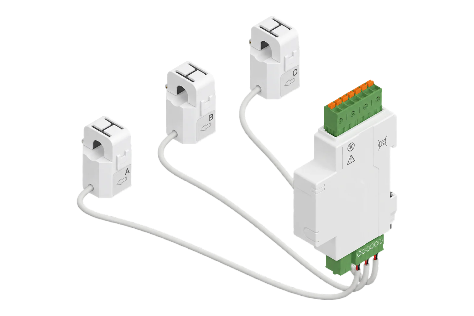
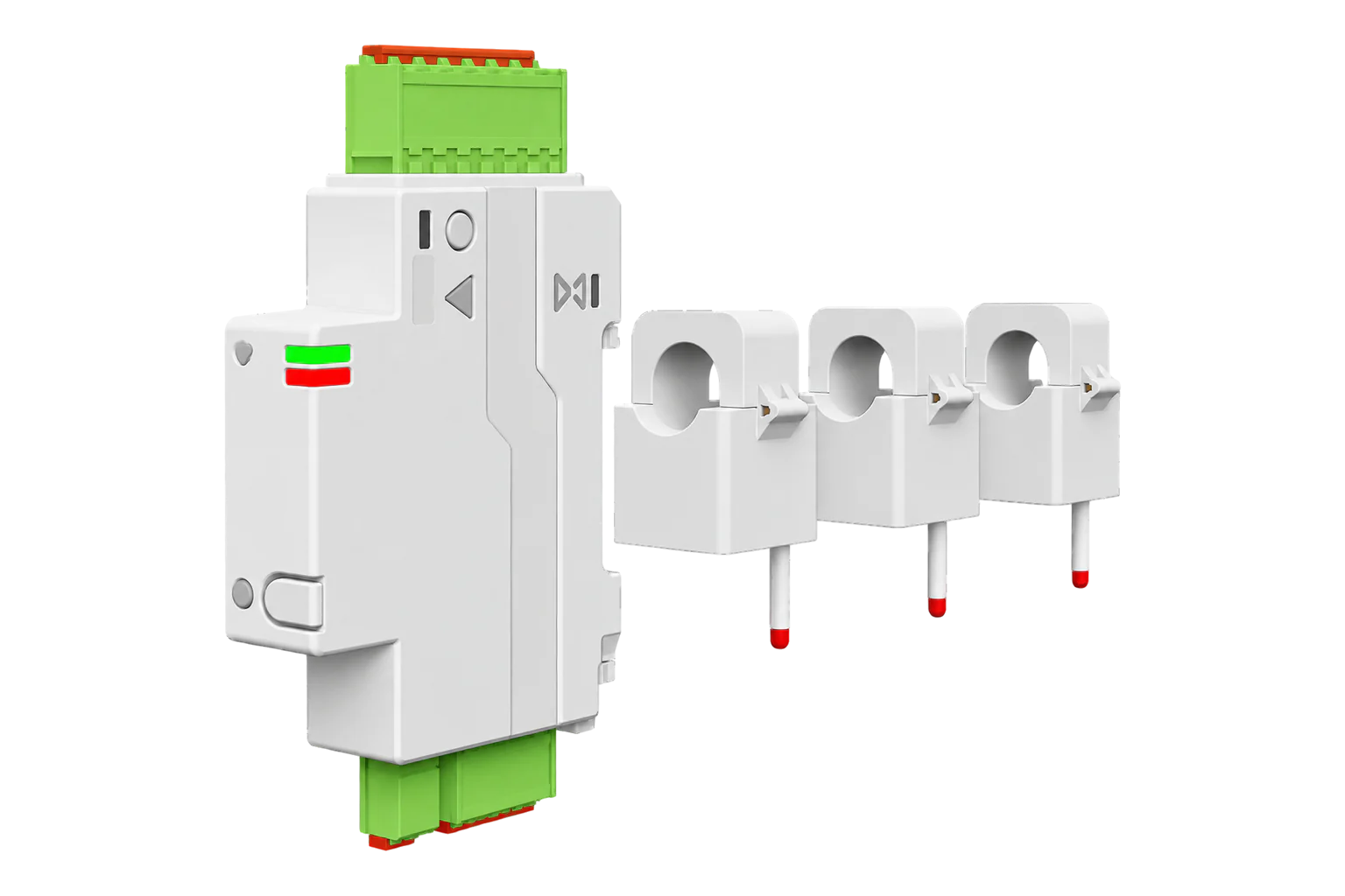
A one-module DIN-rail energy meter with three split-core current clamps, for one three-phase supply or three separate single-phase circuits. NodOn rates it class 1 (±1 %) to IEC 61557-12, from 50 mA to 70 A or 120 A per phase, and it measures in both directions.
- Zigbee
Three-phase CT energy meter
Compatibility
Compatible with EpiSensor Edge over Zigbee.
Pair it with the Zigbee radio on an EpiSensor Gateway. Edge reads it locally on the Gateway.
Edge reads 32 values from it, listed under Interface.
Connect it with
-
Gateway ZGW-20From €899 ex VAT Configure Gateway

Specifications
The SEM-4-3-20 is a DIN-rail meter 18 mm wide with three split-core current transformers that clip around the conductors, so it can be added to an existing board without disconnecting any cables. It takes its supply and its voltage reference from the LA, LB, LC and N terminals, and reports voltage, current, active, reactive and apparent power, power factor, frequency and energy for each phase over Zigbee 3.0.12
- Power
- Self-powered from the measured supply. Takes its supply from the voltage terminals: 220 to 240 V AC line to neutral or 380 to 415 V AC line to line, 2 VA maximum.1
- Poles
- 3P+N, single-phase and three-phase compatible1
- Measurement range
- 50 mA to 70 A per phase (_70A) or 50 mA to 120 A per phase (_120A)1
- Accuracy
- Class 1.0 (±1 %), IEC 61557-121
- Overvoltage category
- III1
- Rated insulation voltage
- 440 V1
- Wireless
- Zigbee 3.0, 2.4 GHz, +10 dBm maximum1
- Wired interface
- Modbus RTU over RS-4851
- Operating temperature
- -25 to 70 °C1
- Protection
- IP20, indoor use1
- Dimensions
- 113.7 × 18 × 65.9 mm (H × W × D) without clamps, one DIN module1
- Weight
- 48 g, plus 3 × 58 g clamps (70 A) or 3 × 72 g clamps (120 A)1
- Order code, 70 A clamps
- SEM-4-3-20_70A, EAN 37003139265121
- Order code, 120 A clamps
- SEM-4-3-20_120A, EAN 37003139265361
Where it is used
Three-phase distribution boards and sub-mains, where one module fits in a single DIN slot and the clamps go on without disconnecting cables.
Transformer and distribution board monitoringSolar PV and battery sites, where separate consumed and produced counters per phase show import and export.
Solar PV monitoringEV charge points, where live power per phase can drive load management against the supply limit.
EV charging load managementThree single-phase tenant or zone circuits from one meter, for cost allocation in shared buildings.
Tenant submetering and cost allocation
Interface
Readings and settings, with units and ranges where NodOn publishes them. readable, writable only.5
| Reading | Unit | Range or values | Access |
|---|---|---|---|
| Measurements 30 | |||
| Total active powerSum of the three phases | W | - | Read only |
| Total reactive powerSum of the three phases | var | - | Read only |
| Total apparent powerSum of the three phases | VA | - | Read only |
| Total consumed energyImported energy, all phases | kWh | - | Read only |
| Total produced energyExported energy, all phases | kWh | - | Read only |
| Active power, phase A | W | - | Read only |
| Active power, phase B | W | - | Read only |
| Active power, phase C | W | - | Read only |
| Voltage, phase ALine to neutral | V | - | Read only |
| Voltage, phase BLine to neutral | V | - | Read only |
| Voltage, phase CLine to neutral | V | - | Read only |
| Current, phase A | A | - | Read only |
| Current, phase B | A | - | Read only |
| Current, phase C | A | - | Read only |
| Power factor, phase A | - | - | Read only |
| Power factor, phase B | - | - | Read only |
| Power factor, phase C | - | - | Read only |
| Reactive power, phase A | var | - | Read only |
| Reactive power, phase B | var | - | Read only |
| Reactive power, phase C | var | - | Read only |
| Apparent power, phase A | VA | - | Read only |
| Apparent power, phase B | VA | - | Read only |
| Apparent power, phase C | VA | - | Read only |
| Consumed energy, phase ACarried on the metering cluster’s tier 1 attribute, not a tariff | kWh | - | Read only |
| Consumed energy, phase BCarried on the tier 2 attribute, not a tariff | kWh | - | Read only |
| Consumed energy, phase CCarried on the tier 3 attribute, not a tariff | kWh | - | Read only |
| Produced energy, phase AExported energy on phase A | kWh | - | Read only |
| Produced energy, phase BExported energy on phase B | kWh | - | Read only |
| Produced energy, phase CExported energy on phase C | kWh | - | Read only |
| Frequency | Hz | - | Read only |
| Controls 2 | |||
| Reset energy countersSets every energy counter to zero; the meter stays on the network | - | reset |
Write only |
| IdentifyFlashes the LED so the unit can be found in a panel | - | identify |
Write only |
Phase A has no suffix in the property names: power, voltage, current, power_factor, power_reactive and power_apparent are phase A, and the _phase_b and _phase_c properties are the other two.5
The meter reuses the metering cluster’s tier 1, 2 and 3 summation attributes for phase A, B and C energy. They are not tariff registers.5
Energy reset uses the Basic cluster’s reset-to-factory-defaults command, which clears the counters but keeps the meter on the network with its bindings and reporting.5
Setup
-
Wire it with the supply isolated
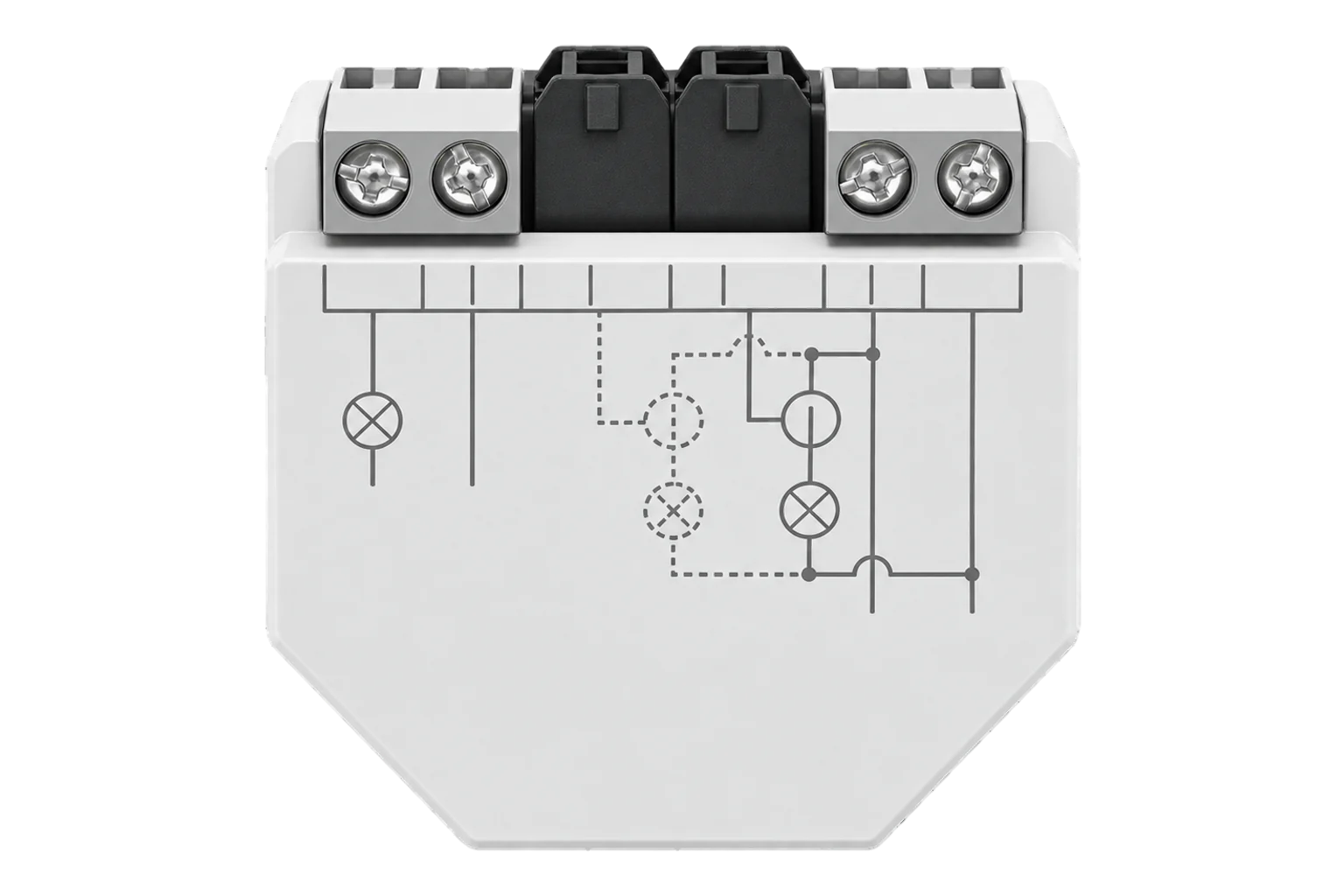
Switch off at the main breaker, clip the meter onto the DIN rail and connect LA, LB, LC and N downstream of an overcurrent protection device. Fit clamp IA on phase A, IB on phase B and IC on phase C, each with its arrow in the direction of current flow.2
-
Power up and check the LED
Close the panel and switch on. A red LED flashing every second means a fault or a wiring error: switch off at once and check the protection device, L and N and the clamps.2
-
Open pairing in Edge
In Edge, open pairing on the Gateway’s Zigbee network.
-
Put the meter into pairing mode
Press and hold the RESET button until the green LED flashes quickly, twice a second. A steady green LED means the meter has joined.2
-
Check each phase
Confirm that Edge identifies it as NodOn SEM-4-3-20, then compare each phase’s current with a clamp meter. A phase that reads export while the load is consuming has its clamp reversed or paired with the wrong voltage.2
Common questions
- Does the SEM-4-3-20 need a NodOn hub to work with Edge?
- No. It is a Zigbee 3.0 device and NodOn states it works with a Zigbee-compatible hub, so it joins the Zigbee radio on an EpiSensor Gateway directly.13
- Can it measure three separate single-phase circuits?
- Yes. NodOn documents a wiring scheme with one clamp on each of three single-phase circuits and L and N as the shared voltage reference. Each clamp then reports as one of the three phases.2
- Does it measure exported energy from solar PV?
- Yes. It measures in both directions and reports consumed and produced energy for each phase and in total. Energy only counts the right way if each clamp’s arrow points in the direction of current flow from the supply.12
- Why are the energy readings wrong after installation?
- NodOn lists three causes: phase and neutral swapped, a clamp paired with the wrong voltage input, or a clamp fitted against the direction of current. Check the connections, the VA-IA, VB-IB and VC-IC pairing and the clamp arrows.2
Related devices
Sources
- 3CT Zigbee Energy Meter SEM-4-3-20 datasheet (opens in a new tab)
- SEM-4-3-20 user guide (opens in a new tab)
- 3CT Zigbee Energy Meter (opens in a new tab)
- NodOn SEM-4-3-20 device documentation (opens in a new tab)
- NodOn SEM-4-3-20 Zigbee definition (opens in a new tab)
Further reading
Product names and trademarks belong to their owners. Publication does not imply endorsement or a commercial relationship.