Milesight UC300
I/O and Modbus controller
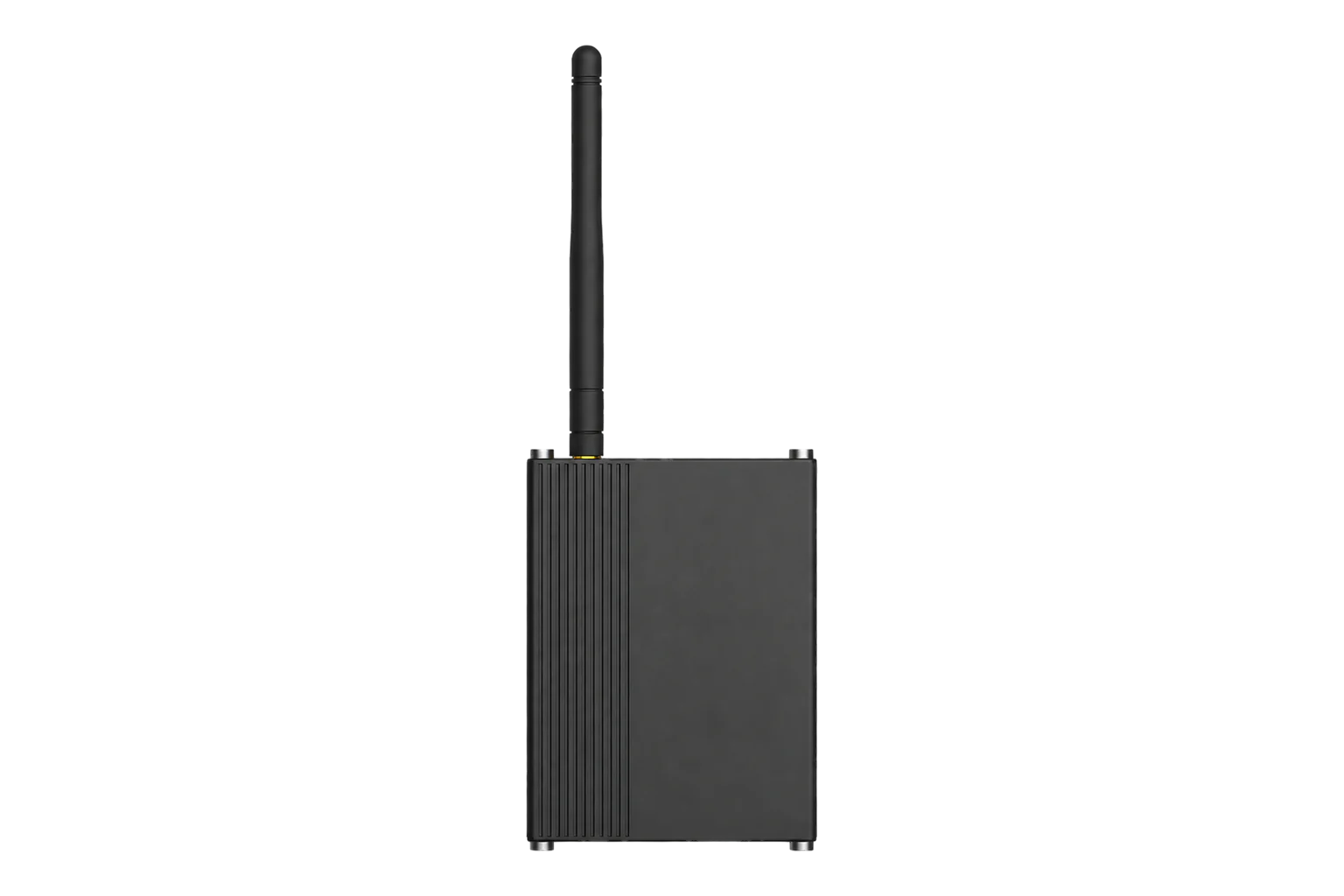
A DIN-rail LoRaWAN controller with four digital or pulse inputs, two relay outputs, two 4-20 mA and two 0-10 V inputs, two PT100 inputs and an RS-485 port that polls up to 32 Modbus RTU registers. It runs from 5 to 24 V DC as a Class C device.
- LoRaWAN
I/O and Modbus controller
Compatibility
Compatible with EpiSensor Edge over LoRaWAN.
Register it on your LoRaWAN network server with its DevEUI and keys. Edge, on the Gateway, reads its decoded uplinks from that server.
Edge reads 9 values from it, listed under Interface.
Connect it with
-
Gateway ZGW-20From €899 ex VAT Configure Gateway

Specifications
The UC300 brings wired signals onto LoRaWAN where running a cable back to a panel is not practical. It has four opto-isolated digital inputs for 3 to 24 V DC signals, each usable as a status input or a pulse counter up to 4,000 Hz, and two SPDT relay outputs rated 3 A at 30 V DC or 250 V AC. Two 4-20 mA inputs, two 0-10 V inputs and two 2- or 3-wire PT100 inputs (-200 to 800 °C) sample at 12-bit resolution.1
- Power
- DC supply. 5 to 24 V DC on a 2-pin terminal block with surge and reverse-polarity protection, or 5 V through USB-C. A power adapter is in the box.1
- Digital inputs
- 4 × opto-isolated, 3 to 24 V DC, digital input or pulse counter up to 4,000 Hz1
- Relay outputs
- 2 × SPDT, 3 A at 30 V DC or 250 V AC1
- Analogue inputs
- 2 × 4 to 20 mA, 2 × 0 to 10 V, 12-bit1
- RTD inputs
- 2 × PT100, 2- or 3-wire, -200 to 800 °C, 12-bit1
- RS-485
- Modbus RTU master or transparent, up to 32 register channels, 1,200 to 115,200 bit/s1
- RS-232
- Transparent, 1,200 to 115,200 bit/s1
- Serial framing
- 8 data bits; no, odd or even parity; 1 or 2 stop bits2
- LoRaWAN
- Class C, OTAA or ABP, versions 1.0.2 and 1.0.32
- Frequency plans
- CN470, IN865, EU868, RU864, US915, AU915, KR920, AS923-1 to AS923-41
- Transmit power
- 16 dBm (868 MHz), 20 dBm (915 MHz), 19 dBm (470 MHz)1
- Antenna
- External, 50 Ω SMA connector1
- Local logic
- Up to 16 IF-THEN commands, 1,000 stored records2
- Operating conditions
- -20 to 60 °C, 0 to 95 % RH non-condensing, IP30 metal case1
- Dimensions
- 93 × 70 × 22 mm without antenna, 142.3 g1
- Mounting
- Desktop, wall or 35 mm DIN rail1
Where it is used
4-20 mA pressure, flow and level transmitters in plant rooms and on process lines, with the scaling set in Edge.
4-20 mA remote monitoring for process instrumentsWater, gas and heat meters with pulse outputs, up to four per controller, counted at up to 4,000 Hz.
Pulse meter remote monitoringA Modbus RTU energy meter or inverter in an outbuilding, polled over RS-485 and sent over LoRaWAN instead of a new cable run.
Modbus meter integration for a BMS or SCADA systemSwitching a pump, a fan or an alarm beacon from a relay, locally by IF-THEN rule or remotely by downlink.
Interface
- Device class
- Class C2
- Regional plans
- EU868, US915, AU915, AS923, KR920, IN865, RU864, CN470
- Activation
- OTAA or ABP
- LoRaWAN version
- 1.0.2 or 1.0.3
- Default uplink interval
- 20 minutes (1 to 1,080 minutes), plus an uplink when a digital input changes
Ports
| FPort | Direction | Carries |
|---|---|---|
| 85 | Uplink | Digital inputs and counters, relay states, analogue and PT100 values, Modbus channel values and read errors, and the information packet sent on joining |
| 85 | Downlink | Relay control, reporting and collection intervals, time, rejoin and reboot |
Decoded fields
Readings and settings, with units and ranges where Milesight publishes them. readable, readable and writable, writable only.3
| Reading | Unit | Range or values | Access |
|---|---|---|---|
| Measurements 6 | |||
| Pulse counters 1 to 4Channels 03 to 06, type C8: unsigned 32-bit, when the input is set as a counter | pulses | - | Read only |
| Digital inputs 1 to 4Channels 03 to 06, type 00. Sent on change and with each report | - | offon |
Read only |
| Current inputs 1 and 2Channels 0B and 0C, type 02: unsigned 32-bit, divided by 100 | mA | 4 to 20 mA | Read only |
| Voltage inputs 1 and 2Channels 0D and 0E, type 02: unsigned 32-bit, divided by 100 | V | 0 to 10 V | Read only |
| PT100 inputs 1 and 2Channels 09 and 0A, type 67: signed 16-bit, divided by 10 | °C | -200 to 800 °C | Read only |
| Modbus channels 1 to 32Channel FF, type 19: one value per channel, in the unit of the connected device | - | - | Read only |
| Controls 1 | |||
| Relay outputs 1 and 2Channels 07 and 08, type 01. Downlink 07 or 08, then 00 or 01, then FF switches a relay | - | offon |
Read and write |
| Settings 1 | |||
| Reporting intervalDownlink channel FF, type 03: unsigned 16-bit | s | 60 to 64,800 s | Write only |
| Diagnostics 1 | |||
| Modbus read errorChannel FF, type 15: the channel that failed to read | - | - | Read only |
RS-232 data does not use port 85. It travels on its own port, set between 2 and 84 or 86 and 223, and so does the optional Modbus pass-through, which carries raw RTU frames between the network server and the RS-485 bus.2
A Modbus value arrives as channel FF, type 19: the channel number counted from 0, the data length, a type byte (bit 7 signed; coil, discrete input, 16-bit, 32-bit or float, input or holding) and the value in little-endian order. A read failure arrives as channel FF, type 15 with the channel number. Each channel reads one value, and a 32-bit value needs its byte order set to match the meter.23
The analogue inputs arrive as unsigned 32-bit values in hundredths: channels 0B and 0C in mA, 0D and 0E in V. Scale them to engineering units in Edge, for example 4 to 20 mA to 0 to 10 bar.23
Counters survive a reboot, but they only count once started from the ToolBox software; until then the controller sends a fixed value.2
Setup
-
Fit the antenna and power it
Screw the LoRaWAN antenna onto the SMA connector and mount it vertically. Connect 5 to 24 V DC to the power terminal block, or 5 V to USB-C.2
-
Register it on the network server
Add the UC300 as a Class C device using OTAA, with the device EUI from its label, the join EUI 24E124C0002A0001 and its application key. In the ToolBox software over USB-C, set the frequency plan and channels to match the network.2
-
Wire and configure the inputs
Wire each signal to its terminal block and enable the interface in ToolBox. Set a digital input to counter mode and press Start for a pulse meter. Click Fetch on each analogue and PT100 input to confirm a sensible value.2
-
Set up the Modbus channels
Match the RS-485 baud rate, parity and stop bits to the meter, fit the 120 Ω terminating resistor with DIP switch 1 on a long or fast bus, then add each channel with its slave ID, register address, type and byte order. Fetch each one and compare it with the meter's display.2
-
Check the decode
Confirm the network server decodes every enabled input and Modbus channel from the next uplink on port 85, and that a relay switches from a downlink, before you connect it to Edge.
Common questions
- How many Modbus registers can it read?
- Up to 32 channels, each one value read from a slave ID and start address. The channels can come from different meters on the same RS-485 bus.12
- Can it read 32-bit and floating-point registers?
- Yes. A channel can be a 16-bit or 32-bit integer or a 32-bit float from input or holding registers, signed or unsigned. Byte order is set per channel: ABCD, CDBA, BADC or DCBA for 32-bit values, AB or BA for 16-bit.23
- Can the relays be switched remotely?
- Yes. As a Class C device the UC300 listens between uplinks, so a downlink of 07 or 08 followed by 00 or 01 and FF switches relay 1 or 2 without waiting for the next report. The relays can also be driven by local IF-THEN rules.235
- Does it work without the network?
- Its IF-THEN rules run locally, so relays still respond to inputs when the network is down. It stores 1,000 records and resends them after the network returns if retransmission is enabled.2
- Can it run on batteries?
- No. It needs 5 to 24 V DC on its terminal block, or 5 V through USB-C.1
Related devices
Sources
- UC300 datasheet (opens in a new tab) (PDF)
- UC300 (LoRaWAN) user guide (opens in a new tab) (PDF)
- UC300 payload decoder and encoder (opens in a new tab)
- UC300 product page (opens in a new tab)
- LoRaWAN 1.0.3 specification (opens in a new tab)
- Milesight UC300 device type definition (opens in a new tab)
Further reading
Product names and trademarks belong to their owners. Publication does not imply endorsement or a commercial relationship.