Milesight CT10x
Single-phase current monitor
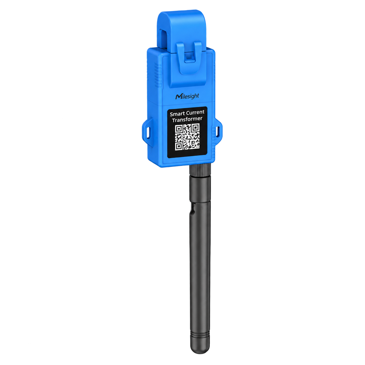
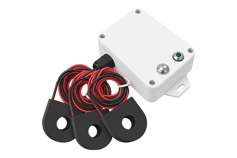
CT101, CT103 and CT105 are self-powered, single-channel LoRaWAN current monitors. Choose by conductor size, rated current and the lowest current that must be reported, not by maximum amperage alone.
- LoRaWAN
Single-phase current monitor
Compatibility
Compatible through LoRaWAN
Milesight documents the CT10x family as LoRaWAN Class A devices and publishes codec definitions for every model. A LoRaWAN gateway and network server deliver decoded telemetry to Edge through a supported IP integration.
This is a protocol-compatible route, not a built-in Edge device mapping. Confirm the exact hardware generation, regional LoRaWAN parameters and network-server decoder. Hardware v2 energy values are estimates calculated from configured voltage and power factor; the CT does not measure either input.
Connect it with
-
Gateway ZGW-20From €899 ex VAT Configure Gateway

For a new or existing private LoRaWAN network
- LoRaWAN
- Platforms
- Edge
When another team already operates the gateway and network server
- LoRaWAN
- Platforms
- Edge
Models
| Models | Interface | Route into Edge |
|---|---|---|
| CT101 · hardware v2 |
| LoRaWAN Class A through a network server; suited to the smallest conductors and lowest-current circuits in this family |
| CT103 · hardware v2 |
| Same LoRaWAN route; use the 250 A datasheet rating rather than treating configuration limits as a rating |
| CT105 · hardware v2 |
| Same LoRaWAN route; larger window and current range, with a higher self-power reporting threshold |
| Earlier hardware | Older manuals publish materially higher minimum reporting currents and a different feature set | Read the hardware and firmware versions from the device and use the matching Milesight documentation and decoder |
Specifications
A split-core current transformer with a LoRaWAN radio inside, powered by the current it measures. The three models differ in rating and aperture: 100 A and 16 mm for the CT101, 250 A and 16 mm for the CT103, 500 A and 36.5 mm for the CT105.1
Interface
Documented measurements and integration boundaries for CT10x.
- RMS current for the single monitored conductor, with minimum and maximum current records
- Accumulated current, documented by Milesight as ampere-hours; preserve the network receive timestamp and rollover behaviour
- Current threshold and over-current alarm states where enabled in the matching device generation
- Optional cable-temperature value and temperature alarm states when the external NTC probe is fitted
- Device, current-sensor and temperature-sensor status values from the matching decoder
- Hardware v2 estimated energy only when reporting type, nominal voltage and load power factor have been deliberately configured
- Hardware and firmware identity for selecting the correct decoder and interpreting generation-specific fields
- No inferred zero: an absent report, collection-failure sentinel or stale timestamp must remain missing or invalid
Assessment
This page covers the CT101, CT103 and CT105. Reporting thresholds and estimated energy differ by model and hardware version.
- InteroperabilityWell supported
- LoRaWAN with published Milesight decoders, read through any compatible network server.14
- AccuracySupported with conditions
- Current is the measurement. Hardware v2 estimates energy from a voltage and power factor you set, so it is not metered energy.123
- SecuritySupported with conditions
- LoRaWAN encrypts and authenticates each device. Protect the device keys, the network-server accounts and the credentials Edge uses.12
- ReliabilitySupported with conditions
- Powered by the current it measures, so there is no wiring to add, but below each model’s threshold it stops reporting. Treat a missing value at low load as a state, not a zero.13
- RuggednessSupported with conditions
- IP30, -20 to +70 °C, 95 % humidity non-condensing, 2.5 kV AC insulation and a UL94 V0 housing: indoor equipment.1
Setup
Decode a CT101 current uplink
This synthetic packet checks the pinned Milesight CT101 and CT101-v2 decoders before mapping network-server data into Edge. It is a decoder example, not a transmitted sensor reading.
- Uplink bytes
- 04 98 B8 0B: channel 04, type 98, two little-endian current bytes.
- Decode
- B8 0B becomes 0x0BB8 = 3000; divide by 100 to obtain 30 A.
- Network-server field
- Map the decoded current field in A with the device identity and uplink timestamp. The network server and OEM decoder remain between the sensor and Edge.
- Missing measurement
- 04 98 FF FF produces current_sensor_status rather than a current value. Keep that reading missing; do not report 0 A or scale 65535.
Acceptance: Use the matching CT101 decoder as the starting point, then compare a live decoded current with a reference instrument. Preserve the model-specific type and divisor when adding other CT models. Accumulated current is Ah; energy based on configured voltage and power factor remains an estimate.
-
Confirm CT101, CT103 or CT105, record the hardware and firmware versions, and select the matching base or v2 decoder before field mapping.
Retain representative raw and decoded payloads because current manuals and decoder code differ in some optional wire types.
-
Have a qualified installer isolate the circuit as required, clamp the CT around one insulated conductor only, and verify that the aperture closes fully.
-
Check the expected lowest operating current against the model's reporting threshold at the chosen interval.
A self-powered CT below that level may not produce a usable report.
-
Provision the correct regional frequency plan, activation mode and unique LoRaWAN credentials; then verify uplink counters and timestamps at the network server.
-
Compare live current with a suitable reference instrument at representative low and normal loads, and confirm sign, units, scaling and alarm semantics after decoding.
-
If using hardware v2 energy reporting, document the configured nominal voltage and power factor as assumptions.
Reconcile the result against a true energy meter before using it for decisions.
-
If USB power is needed below the self-power threshold, confirm the approved accessory arrangement: the Type-C connection is also used by the optional NTC probe, and Milesight's documentation does not establish simultaneous USB power and temperature sensing.
-
Test stale-data and sensor-failure handling by interrupting reports.
Dashboards and alerts must distinguish missing telemetry from a measured zero.
-
If temperature is required, confirm that the optional NTC probe is installed and validate its location and plausible reading; a codec field does not prove that a probe is fitted.
Common questions
- Why does a CT10x stop reporting at low load?
- It draws its power from the conductor it measures. Below the minimum current in the model table (1.5 A for the CT101 at a one-minute interval, for example) it cannot power the radio, so a missing value at low load is a state, not a zero.1
- Is the energy value a metered reading?
- No. Hardware v2 estimates energy from the measured current and a voltage and power factor you configure. For metered energy use a meter with voltage inputs.2
Related devices
Sources
- CT10x LoRaWAN Smart Current Transformer (opens in a new tab)
- CT10x configurable properties (opens in a new tab)
- Milesight IoT device release notes (opens in a new tab)
- CT-series codec source (opens in a new tab)
- ct101 OEM decoder at pinned revision (opens in a new tab)
- ct101-v2 OEM decoder at pinned revision (opens in a new tab)
Further reading
Product names and trademarks belong to their owners. Publication does not imply endorsement or a commercial relationship.