Milesight CT3xx
Three-phase current monitor
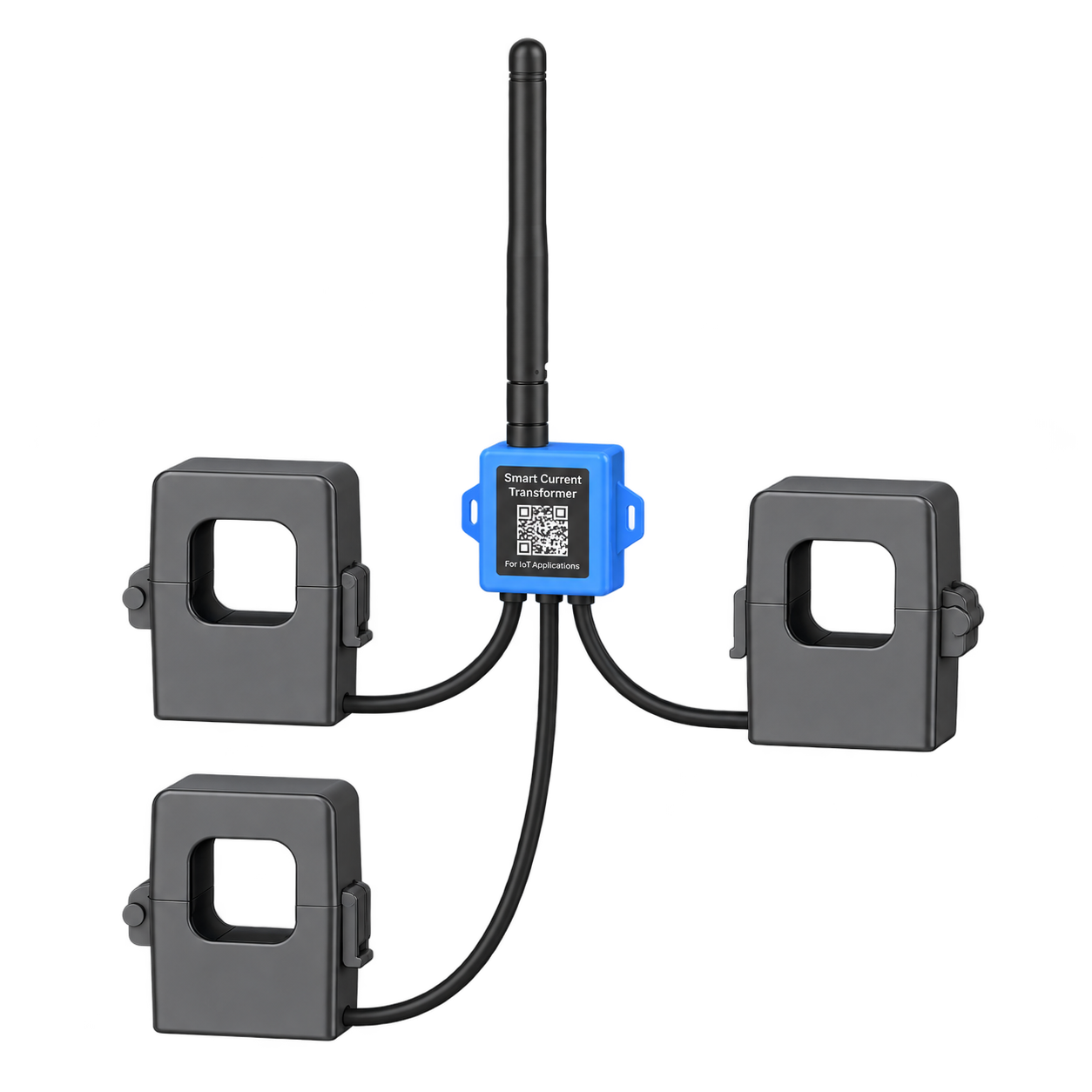
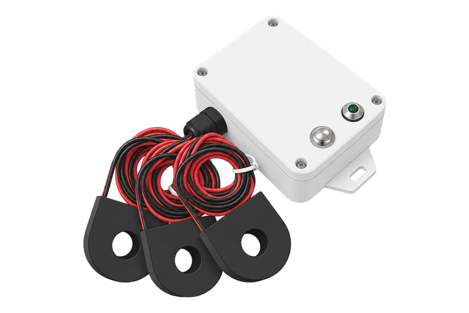
CT303, CT305 and CT310 combine three split-core current channels in one LoRaWAN device. Model choice sets aperture, rated current and the lowest self-powered current that the system can report reliably.
- LoRaWAN
Three-phase current monitor
Compatibility
Compatible through LoRaWAN
Milesight documents the CT3xx family as LoRaWAN Class A devices and publishes model-specific codecs with three current channels. A LoRaWAN gateway and network server deliver decoded telemetry to Edge through a supported IP integration.
This is a protocol-compatible route, not a built-in Edge device mapping. Confirm the exact hardware generation, regional LoRaWAN parameters, phase assignment and network-server decoder. Hardware v2 energy values are estimates from configured voltage and power factor, not measurements of either input.
Connect it with
-
Gateway ZGW-20From €899 ex VAT Configure Gateway

For a new or existing private LoRaWAN network
- LoRaWAN
- Platforms
- Edge
When LoRaWAN infrastructure is already managed centrally
- LoRaWAN
- Platforms
- Edge
Models
| Models | Interface | Route into Edge |
|---|---|---|
| CT303 · hardware v2 |
| Three LoRaWAN current channels through a network server; best low-current visibility in the family |
| CT305 · hardware v2 |
| Same LoRaWAN route with a larger conductor window and mid-range rating |
| CT310 · hardware v2 |
| Same LoRaWAN route for the largest conductors and highest currents in the family |
| Earlier hardware | Older manuals publish materially higher minimum reporting currents and a different feature set | Read the hardware and firmware versions and keep the matching documentation, decoder and acceptance payload together |
Specifications
A three-phase current monitor: one LoRaWAN transmitter with three split-core clamps, powered from phase A. The models differ in rating and aperture: 300 A for the CT303, 500 A for the CT305 and 1000 A for the CT310.13
Interface
Documented measurements and integration boundaries for CT3xx.
- Independent RMS current for phase A, phase B and phase C, including per-phase minimum and maximum records
- Accumulated current for each phase, documented by Milesight as ampere-hours; preserve network receive timestamps and rollover behaviour
- Per-phase current threshold, over-current and sensor-status indications where enabled in the matching generation
- Optional cable-temperature value and temperature alarm states when the external NTC probe is fitted
- Hardware v2 per-phase estimated energy only when reporting type, nominal voltage and load power factor have been deliberately configured
- Hardware and firmware identity for choosing the matching base or v2 decoder
- Collection-failure sentinels and stale reports retained as invalid or missing, never converted to zero
- No measured voltage, measured power factor, active power, reactive power or revenue-grade energy value from the CT alone
Assessment
This page covers the CT303, CT305 and CT310. Reporting thresholds and estimated energy differ by model and hardware version.
- InteroperabilityWell supported
- LoRaWAN with published Milesight decoders, read through any compatible network server.16
- AccuracySupported with conditions
- Three current channels show how the phases are loaded. Hardware v2 estimates energy from a voltage and power factor you set, not from measured voltage.145
- SecuritySupported with conditions
- LoRaWAN encrypts and authenticates each device. Protect the device keys, the network-server accounts and the credentials Edge uses.12
- ReliabilitySupported with conditions
- Milesight documents phase A as its power source. If that phase loses load, every channel can stop reporting, so treat a missing value as a state, not a zero.13
- RuggednessSupported with conditions
- IP30, 3 kV AC insulation and a UL94 V0 housing. The transmitter runs from -20 to +70 °C and the clamps from -40 to +55 °C: indoor equipment.1
Setup
Decode a CT303 current uplink
This synthetic packet checks the pinned Milesight CT303 and CT303-v2 decoders before mapping network-server data into Edge. It is a decoder example, not a transmitted sensor reading.
- Uplink bytes
- 04 99 B8 0B: channel 04, type 99, two little-endian current bytes.
- Decode
- B8 0B becomes 0x0BB8 = 3000; divide by 10 to obtain 300 A.
- Network-server field
- Map the decoded current_chn1 field in A with the device identity and uplink timestamp. The network server and OEM decoder remain between the sensor and Edge.
- Missing measurement
- 04 99 FF FF produces current_chn1_sensor_status rather than a current value. Keep that reading missing; do not report 0 A or scale 65535.
Acceptance: Use the matching CT303 decoder as the starting point, then compare a live decoded current with a reference instrument. Preserve the model-specific type and divisor when adding other CT models. Accumulated current is Ah; energy based on configured voltage and power factor remains an estimate.
-
Confirm CT303, CT305 or CT310, record hardware and firmware versions, and select the matching base or v2 decoder before defining points.
Retain representative raw and decoded payloads because current manuals and decoder code differ in some optional wire types.
-
Have a qualified installer isolate the circuit as required, place each CT around one insulated phase conductor only, and verify that every split core closes fully.
-
Map the labelled phase-A, phase-B and phase-C clamps to the site's phase references.
Do not put a phase and neutral together through one CT.
-
Connect phase A even when only a subset of channels is required: Milesight documents phase A as the self-power source, so its absence can power the device off.
-
Check the lowest expected phase-A current and the other phase currents against the selected model's hardware-v2 reporting thresholds at the chosen interval.
-
Provision the correct regional frequency plan, activation mode and unique LoRaWAN credentials; verify counters, timestamps and all three decoded channels at the network server.
-
Compare each phase with a suitable reference instrument under representative load, deliberately swapping or interrupting one input to prove phase labels and failure handling.
-
If using hardware v2 energy reporting, record nominal voltage and power factor as configuration assumptions and reconcile estimates with a true multi-function energy meter.
-
If USB power is needed below the phase-A self-power threshold, confirm the approved accessory arrangement: the Type-C connection is also used by the optional NTC probe, and Milesight's documentation does not establish simultaneous USB power and temperature sensing.
-
Test missed uplinks, the documented current collection-failure sentinel and stale timestamps.
Alarms and dashboards must not present any of them as measured zero.
-
If temperature is required, confirm that the optional NTC probe is installed and validate its position and plausible reading.
-
Save the device configuration, decoder revision, phase map, reference readings and accepted raw/decoded payloads as the commissioning record.
Common questions
- Which phase powers the CT3xx?
- Phase A. Clamp it on the conductor that carries load most of the time, because when that phase drops below the minimum current all three channels stop reporting.3
- Does it measure power or energy?
- It measures current on each phase. Hardware v2 estimates energy from a voltage and power factor you configure, not from measured voltage, so treat that value as an estimate.2
Related devices
Sources
- CT3xx LoRaWAN Smart Current Transformer (opens in a new tab)
- CT3xx configurable properties (opens in a new tab)
- CT3xx installation instructions (opens in a new tab)
- CT3xx uplink data definition (opens in a new tab)
- Milesight IoT device release notes (opens in a new tab)
- CT-series codec source (opens in a new tab)
- ct303 OEM decoder at pinned revision (opens in a new tab)
- ct303-v2 OEM decoder at pinned revision (opens in a new tab)
Further reading
- ApplicationTransformer and distribution board monitoring
- GuideSelecting current transformers
- GuideHigh-accuracy electricity metering
- ToolThree-phase power calculator
- ToolkW to amps calculator
- GuideUsing Zigbee alongside LoRaWAN
- ManufacturerMilesight devices
- ProtocolLoRaWAN devices
- CategoryCurrent transformers
Product names and trademarks belong to their owners. Publication does not imply endorsement or a commercial relationship.