4-20 mA remote monitoring for process instruments
Current-loop and voltage instruments read by a mains-powered analogue signal sensor, with the range, the scaling and the fault current recorded beside the value.
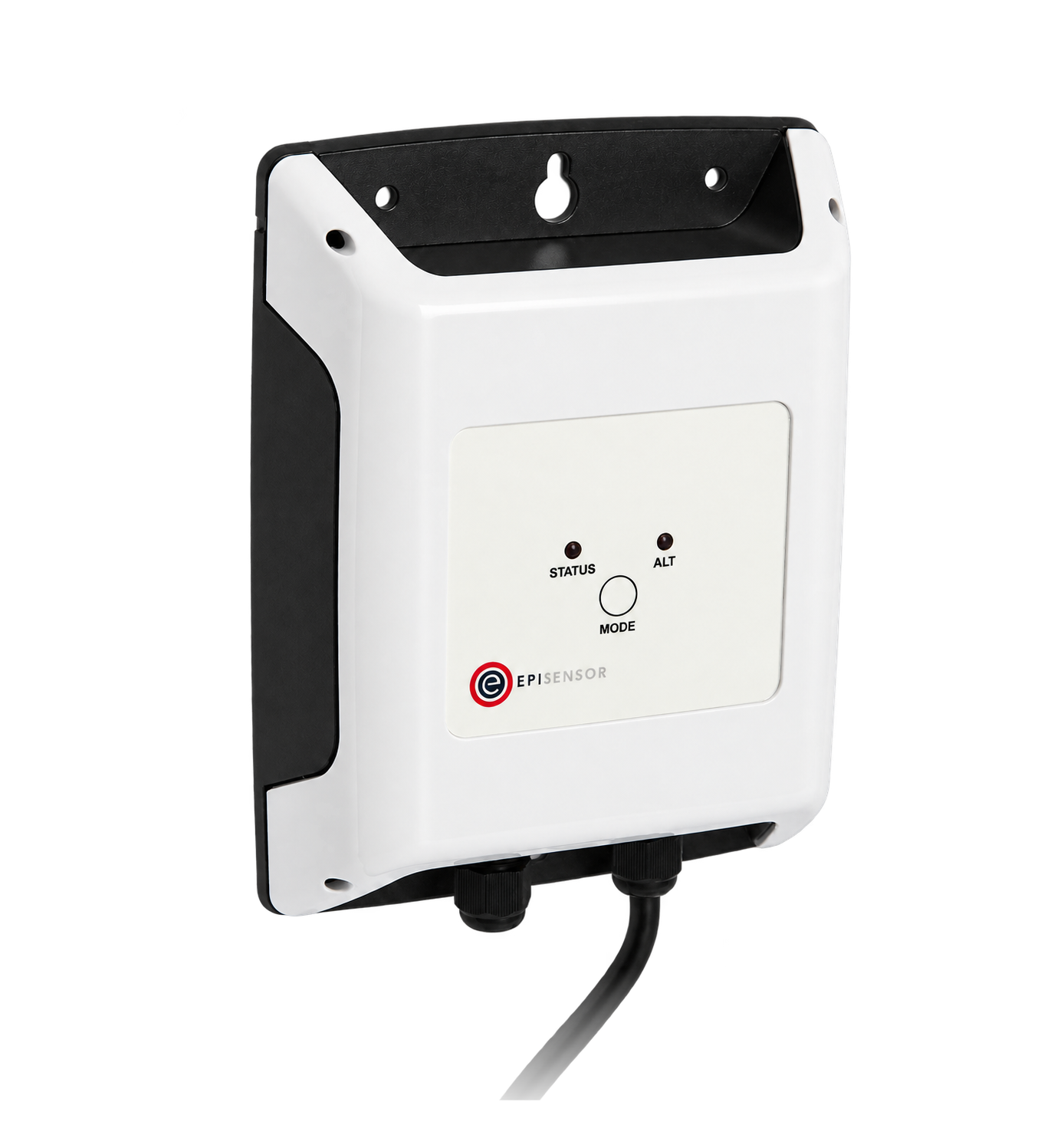

- Measure
- 4-20 mA transmitters, 0-10 V signals, process and ambient temperature, and the machine states beside them
- Good practice
- Industrial process monitoring keeps the raw signal beside the engineering value
- Sensors
- ZIO-22, two current loops, 0 to 20 mA at 0.001 mA, up to 36 V DC Analogue Signal Sensor datasheet
- On site
- ZGW-20 Gateway, scaling, quality rules and onward integration Gateway datasheet
Hardware for 0-10 V signal monitoring and current loops
One interface per signal type. Both are mains powered, because a loop input cannot also run on a battery.
Pressure, flow, level and other 4-20 mA transmitters
1 per pair two externally powered loops
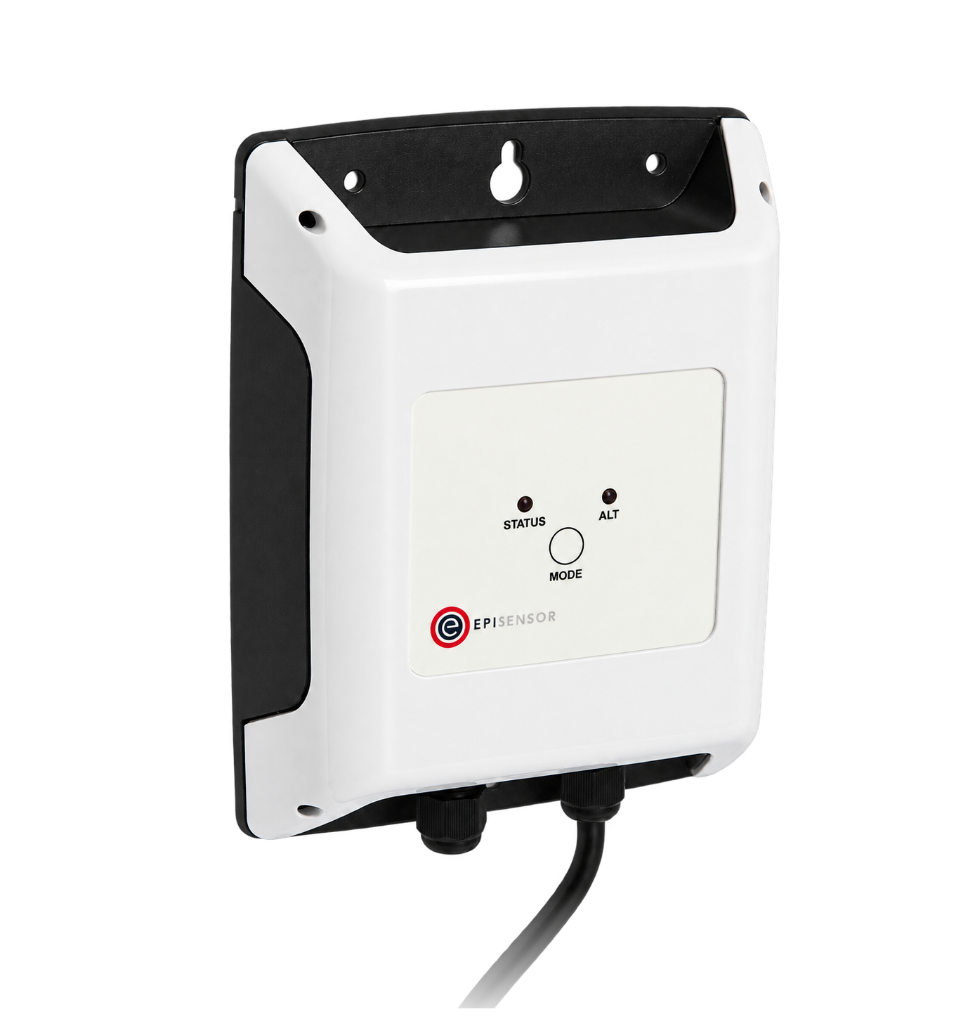
0 to 20 mA at 0.001 mA resolution, up to 36 V DC, 85 to 264 V AC supply, IP67
Instruments whose output is 0 to 10 V rather than a current loop
1 per signal 0 to 10 V, one channel
0 to 10 V DC at 0.001 V resolution
Scales each signal once, keeps the raw value beside it, and applies the quality rules
1 per site up to 250 wireless devices
Where temperature is part of the measurement
Process, vessel or ambient temperature where a probe can reach it directly
1 per point 1.5 m waterproof probe
 1 waterproof probe, 1.5 m lead
±0.2 °C from −20 to 70 °C, ±0.5 °C from −40 to 105 °C
If the states come from a controller rather than a contact

Machine states and recipe or alarm registers from a controller
1 per controller up to 30 registers
What travels with an analogue signal
A current is not a measurement until its range, its scaling and its fault behaviour are written down with it.
From field measurement to Edge
Each field signal reaches its named EpiSensor interface, reports through the site Gateway and is handled locally in Edge.
- Wired
- Zigbee
- Edge
- Platforms
| Position | What it tells you | Reference | Sensor |
|---|---|---|---|
| Loop-current instruments | Pressure, flow, level and anything else on 4-20 mA | Loop supply, total burden and whether the arrangement sources or sinks Analogue Signal Sensor datasheet | ZIO-22 (on this page) |
| Voltage-output instruments | Signals that arrive as 0 to 10 V | Common reference, input impedance and whether zero volts is a valid reading or a fault Analogue Signal Sensor datasheet | ZVO-20 (on this page) |
| Temperature points | Process, vessel, pipe or ambient temperature at a declared position | Probe construction, immersion and response time matched to the process Probe Temperature Sensor datasheet | TES-21 (on this page) |
| Machine and controller states | What the plant was doing when the analogue value moved | Documented contacts or verified registers, with the state map recorded Modbus Interface datasheet | ZMB-31 (on this page) |
Classify under-range using the transmitter's fault thresholds. A current below 4 mA is outside the normal 4-20 mA span, but it is not automatically a transmitter fault or a valid zero-process reading. For an NE 43-configured transmitter, check the documented failure threshold at or below 3.6 mA or at or above 21 mA, and handle the intervening under-range separately.
Add up the loop voltage budget. Transmitter minimum, receiver and cable drops all take a share of the supply. Add them up before you find out on site.
Settings that belong with every analogue point
Each of these is a number from the instrument's datasheet, recorded once and used everywhere.
| Setting | Typical value | Where to check |
|---|---|---|
| Loop supply | 24 V DC, external | The loop's own power supply. The interface reads the current and does not power the loop. |
| Voltage budget | Supply minus transmitter minimum and every drop | The transmitter's minimum terminal voltage and the total cable resistance, before installation. |
| Range | 4 mA and 20 mA endpoints in engineering units | The transmitter's configuration, not the process's expected range. |
| Scaling | Linear between the endpoints | The value in Edge against the transmitter's display at two points. |
| Fault current | At or below 3.6 mA or at or above 21 mA | The transmitter's NAMUR NE 43 or other fault setting, and what Edge does with it. |
| Reporting interval | 1 to 15 minutes | Edge sensor settings, chosen for how fast the process actually moves. |
| Stale threshold | Longer than the reporting interval | Calculated sensors default to five minutes. Raise that threshold when the source reports less often, so a healthy 15-minute point is not treated as stale between readings. |
Commissioning checks
Every one of these is about making a plausible number provable.
-
Each channel is traced end to end
Follow every signal from the instrument tag to the point name and unit in Edge.
Pass when the tag, the wire, the channel and the point name all agree.
-
Two known values are read back
Use the transmitter's simulation mode, or a known process condition, at two points in the range.
Pass when the raw current and the scaled value are both right, with the rounding understood.
-
The loop has headroom
Add up the transmitter minimum, the receiver and the cable drops at 20 mA.
Pass when the supply covers all of them with margin, calculated before installation.
-
A fault reads as a fault
Force the documented fault current, or disconnect the loop.
Pass when Edge shows a fault or a gap rather than an ordinary minimum or maximum reading.
-
Stale data is withheld
Break one signal path for longer than the stale threshold.
Pass when the value stops rather than repeating, and anything calculated from it stops too.
Limits of this measurement
The interface reads a signal faithfully. Everything upstream of it is still the instrument's responsibility.
- Monitoring does not certify instrument suitability, hazardous-area protection, functional safety or process containment.
- A protocol or signal type in common does not prove compatibility with a particular model, wiring option or register map.
- Scaling cannot recover accuracy lost to a poor sensor position, an unsuitable range or an unquantified installation error.
- An analogue value carries no quality flag of its own: the fault behaviour has to be configured deliberately.
Sources
- Fundamentals of the 4-20 mA current loop (opens in a new tab) (opens in a new tab) NI
- Modbus serial line protocol and implementation guide (opens in a new tab) Modbus Organization
- Memograph M operating instructions, NAMUR NE 43 fault mode (opens in a new tab) Endress+Hauser
- Analogue Signal Sensor datasheet (opens in a new tab) EpiSensor. Specifications, ranges and ordering codes.
Related
- OverviewEnergy monitoring
- CalculatorRTD lead resistance error calculator
- GuideCommissioning 4-20 mA and 0-10 V monitoring
Third-party devices for this application
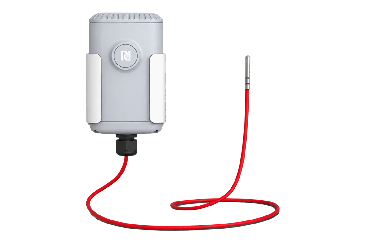
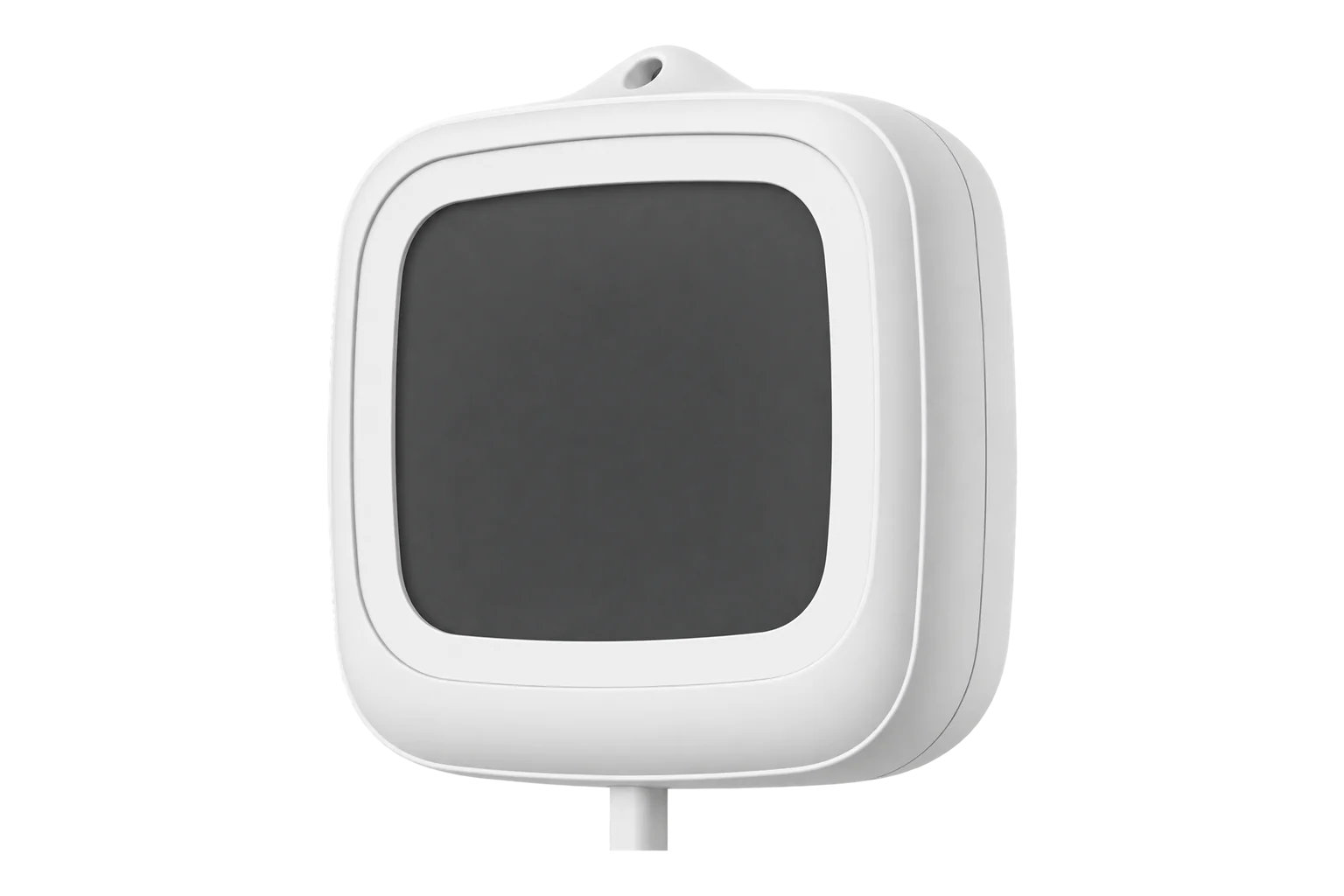
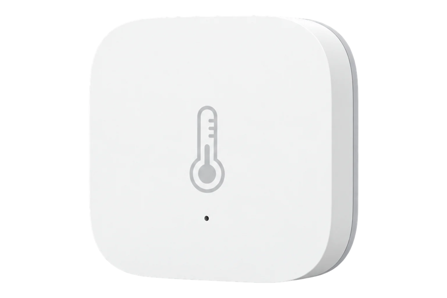
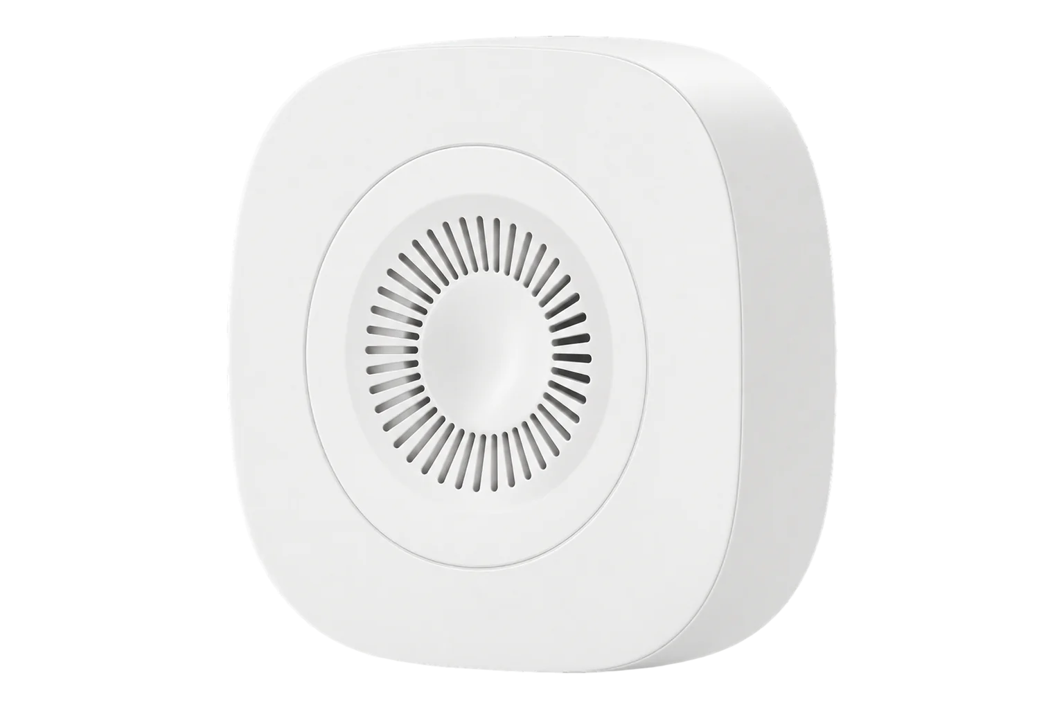
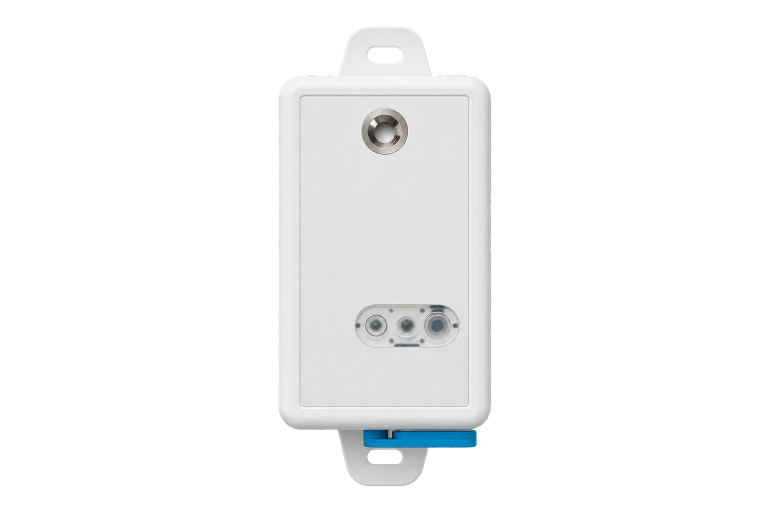
More in the Device Directory: Temperature and humidity sensors (21)
Get the loop budgets and the scaling right first time
An engineer can check the loop budgets, pick the interfaces, and write the scaling down with you.