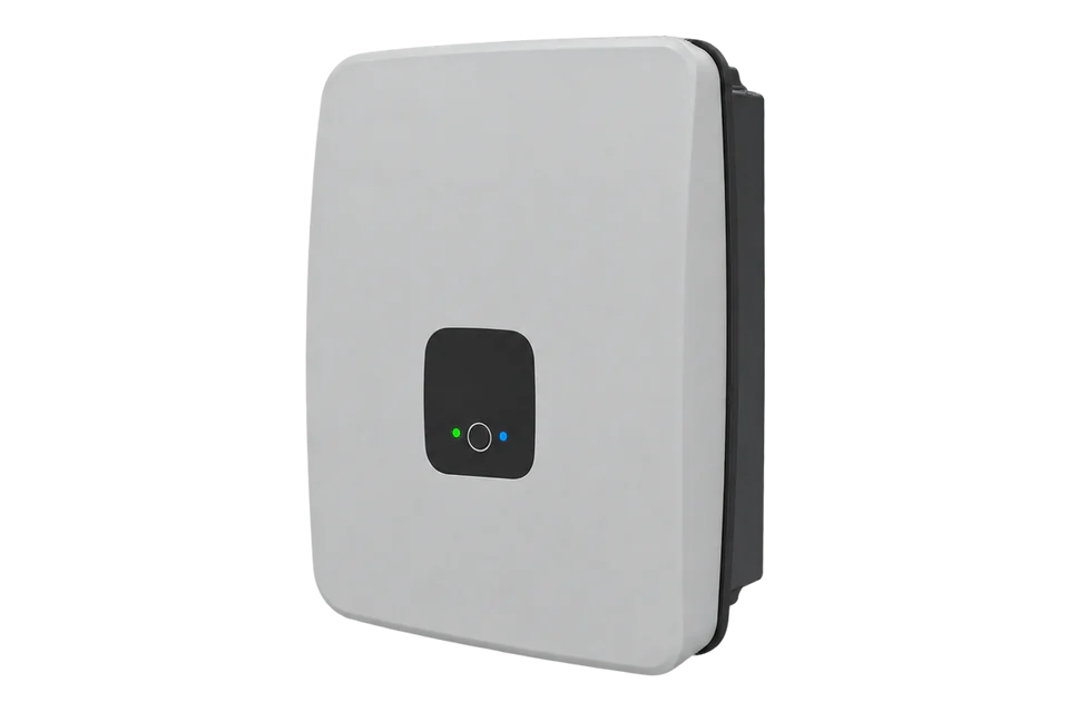
Ingeteam SUN STORAGE 1Play TL M
Single-phase hybrid solar inverter
The INGECON SUN STORAGE 1Play TL M is a single-phase hybrid inverter with two MPPTs, a battery input for lead-acid or lithium-ion batteries and a backup output for critical loads, in 3, 4.5 and 6 kW ratings. Its built-in EMS speaks Modbus TCP, and Ingeteam publishes the input-register map: battery voltage, current, power, SOC and SOH, PV power, grid and load power, temperatures and status, read with FC04. Edge reads them over Ethernet or Wi-Fi on port 502.
Compatibility
Compatible with EpiSensor Edge over Modbus TCP
Ingeteam's 1Play input-register document ABH2010IMB02 defines the online data as input registers read with function 0x04, numbered from 30001 at memory position 0. The 1Play TL M manual states that the inverter's EMS uses Modbus-TCP on port 502 and sets the polling limits. Edge is a Modbus TCP client and reads those registers directly.
INGECON SUN STORAGE 1Play 3TL M, 4.5TL M and 6TL M under input-register document ABH2010IMB02 revision K and manual ABH2014IQM02 revision A. Site check: read the battery block at 30015 to 30018 and compare voltage and SOC with the web application. Poll no faster than once a second and no more than 10 registers per request. The RS-485 port serves the inverter's own wattmeter, not Edge. Read-only monitoring; no charge, discharge or export settings.
Connect it with

On every 1Play TL M, through its Ethernet TCP connector J10 or its Wi-Fi client connection
- Modbus
- Edge
- Platforms
Models
| Models | Interface | Route into Edge |
|---|---|---|
| INGECON SUN STORAGE 1Play 3TL M | 3 kW rated, 13 A maximum AC current | Modbus TCP, input-register map ABH2010IMB02. |
| INGECON SUN STORAGE 1Play 4.5TL M | 4.5 kW rated, 20 A maximum AC current | Modbus TCP, input-register map ABH2010IMB02. |
| INGECON SUN STORAGE 1Play 6TL M | 6 kW rated, 26 A maximum AC current | Modbus TCP, input-register map ABH2010IMB02. |
| INGECON SUN STORAGE 100TL and other three-phase Ingeteam storage inverters | Different register maps | Use the matching guide or Ingeteam document; the 1Play addresses do not transfer. |
Specifications
The 1Play TL M combines a two-MPPT PV input, a 40 to 460 V battery input and a backup output, and runs stand-alone, self-consumption and UPS modes. The built-in EMS manages self-consumption with an external wattmeter on RS-485 and can control EV chargers over Modbus TCP or Wi-Fi.23
- Rated power
- 3 kW (3TL M), 4.5 kW (4.5TL M), 6 kW (6TL M) at 230 V, 50 / 60 Hz3
- Battery input
- 40 to 460 V; 66 A maximum charge and discharge current; lead-acid or lithium-ion, CAN Bus 2.0 to lithium-ion BMS3
- PV input
- 11.5 kWp maximum; 2 MPPTs, 80 to 480 V MPP range, 550 V maximum, 15 A per input3
- Backup output
- 6,400 / 6,900 / 7,900 W for 30 min, 2 min and 3 s at 25 °C; 12 ms response time3
- Communication
- Wi-Fi and Ethernet; RS-485 for the wattmeter; CAN Bus 2.0 for the BMS; 2 digital inputs and 2 potential-free outputs2
- Modbus read
- FC04 Read Input Registers from 30001 (memory position 0); TCP port 502; at least 1 s between requests and at most 10 registers per request13
- Environment
- IP65; -20 to +65 °C; 4 to 100% relative humidity, non-condensing; 2,000 m maximum altitude; 26 kg; 470 x 360 x 180 mm3
Interface
Documented measurements and integration boundaries for SUN STORAGE 1Play TL M.
- Total operation time at 30007 and 30008 (wire 6 and 7), UINT32 in hours. The map does not state the word order; check it against the web application before trusting it.
- Inverter Alarms at 30011 and 30012 (wire 10 and 11), UINT32 bit field.
- Inverter Status at 30013 (wire 12), UINT16 bit field: bit 0 connected to the grid, bit 1 inverter running, bit 2 stand-by on, bit 3 current source, bit 4 waiting to connect, bit 5 emergency charge, bit 6 internal bypass closed. 0x0B is on-grid and 0x02 is off-grid.
- Battery voltage at 30015 (wire 14), UINT16 in V x 10; battery current at 30016 (wire 15), INT16 in A x 100; battery power at 30017 (wire 16), INT16 in W.
- Battery SOC at 30018 (wire 17) and SOH at 30019 (wire 18), UINT16 in %.
- Battery maximum charging and discharging current at 30020 and 30021 (wire 19 and 20), UINT16 in A x 100; battery status at 30022 (wire 21): 0 stand-by, 1 discharging, 2 constant-current charging, 3 constant-voltage charging, 4 floating, 5 equalising, 6 BMS communication error, 7 not configured, 8 and 9 capacity calibration.
- Battery temperature at 30023 (wire 22), INT16 in °C x 10.
- PV voltage at 30024 (wire 23) in V, PV current at 30025 (wire 24) in A x 100, PV power at 30026 (wire 25) in W, all UINT16.
- AC loads voltage at 30027 (wire 26) in V, current at 30028 (wire 27) in A x 100, frequency at 30029 (wire 28) in Hz x 100, active power at 30030 (wire 29) in W and reactive power at 30031 (wire 30) in VAr.
- Inverter cosine of phi at 30032 (wire 31) x 1000, inverter active power at 30033 (wire 32) in W and reactive power at 30034 (wire 33) in VAr.
- Grid or genset voltage at 30035 (wire 34) in V, current at 30036 (wire 35) in A x 100, frequency at 30037 (wire 36) in Hz x 100, active power at 30038 (wire 37) in W and reactive power at 30039 (wire 38) in VAr.
- Positive reactive power means the current lags the voltage; cosine of phi is given as an absolute value. The map does not state the sign of active power or battery current, so set it from a known charge and a known export.
- DC bus voltage at 30040 (wire 39) in V; heatsink, IC and PT100 temperatures at 30041 to 30043 (wire 40 to 42) in °C x 10.
- Battery BMS alarm bits at 30048 (wire 47), added in revision K, and residual current at 30049 (wire 48) in mA.
- Active power reduction reason at 30060 (wire 59) and ratio at 30061 (wire 60) in % x 10, for example reason 7 self-consumption or 9 battery power limited.
- The map lists the firmware version from which each register exists; Inverter Status needs firmware version _W and battery status _Y. Registers 30052, 30059, 30063 and 30064 are reserved.
Assessment
INGECON SUN STORAGE 1Play 3TL M, 4.5TL M and 6TL M, read-only Modbus TCP under input-register document ABH2010IMB02 revision K.
- InteroperabilitySupported with conditions
- Ingeteam publishes the input-register map with types, scales, the 30001 offset and a since-firmware column. The manual gives the port and polling limits but not the unit identifier, and recommends a single client.13
- AccuracyLimited
- Battery, PV, grid and load values have explicit scales and the reactive sign convention is stated. The map has no energy counters, does not state the active-power sign, and gives power in whole watts with no stated accuracy.1
- SecurityLimited
- Configuration needs the installer login and the Wi-Fi access point uses the password on the inverter label. The Modbus TCP port has no documented authentication, so restrict it to the local monitoring network.3
- ReliabilitySupported with conditions
- The datasheet lists its protections and the EMC and safety standards it is built to. The manual warns that requests outside the polling limits may not return correct data, so Edge must poll gently and keep failed reads stale.23
- RuggednessWell supported
- IP65 for indoor and outdoor installation, -20 to +65 °C, 4 to 100% humidity and 2,000 m altitude are published.23
- ScalabilityLimited
- Each inverter is a separate endpoint with a one-client recommendation, at most 10 registers per request and at least one second between requests, which limits fast polling across many sites.3
Setup
Read the battery block from 30015
Document ABH2010IMB02 revision K numbers input registers from 30001, which is memory position 0, and reads them with function 0x04. Battery voltage, current, power and SOC sit at 30015 to 30018. The bytes below are computed from that map as a synthetic decoder check, not captured from an inverter.
- Target
- Inverter IP address, TCP port 502, the Modbus node from the inverter's settings
- Address convention
- Wire address = register number minus 30001: register 30015 is address 14 (0x000E). Sending 15 starts one register late and reads current as voltage.
- Request PDU
- 04 00 0E 00 04: FC04, address 0x000E, four registers, inside the 10-register limit. The TCP client adds the MBAP header.
- Response PDU
- 04 08 02 00 0F 42 07 D0 00 40: eight data bytes.
- Decode
- Voltage 0x0200 = 512, so 51.2 V; current 0x0F42 = 3906, so 39.06 A; power 0x07D0 = 2000, so 2,000 W; SOC 0x0040 = 64, so 64%.
- Consistency
- 51.2 V x 39.06 A = 2,000 W, so voltage, current and power agree. A negative current or power reads as 0x8000 or above and must be decoded as INT16.
Acceptance: Keep the points when voltage and SOC match the web application. Then record which sign is charging. These bytes are a synthetic decoder check, not a reply from a physical inverter.
-
Identify the model and firmware
Record the rating from the nameplate (3TL M, 4.5TL M or 6TL M), the inverter firmware and the battery. The register map gives the firmware version from which each register exists, so check the firmware before polling status and battery status.
-
Connect the inverter to the network
Use the Ethernet TCP cable on connector J10 or join the inverter to a Wi-Fi network from the web application. The inverter uses DHCP by default; reserve its address or set a static one.
-
Check for an existing client
Ingeteam recommends a single client on port 502. If a monitoring or EV charging system already polls the inverter over Modbus TCP, agree with its owner before Edge connects, and keep the combined request rate within the manual's limits.
-
Read the battery block
Create a read-only Modbus TCP connection to port 502 and read four input registers from 30015 (wire address 14) with FC04. Read the Modbus node from the inverter's communication settings. Apply V x 10 to voltage, A x 100 to current, W to power and % to SOC.
-
Add PV, grid and load points in small blocks
Group the remaining reads into blocks of no more than 10 registers, for example 30024 to 30031 and 30033 to 30040, polled every few seconds rather than continuously. Record the sign of battery and grid power during an existing charge and an existing export.
Common questions
- Can Edge use the 1Play RS-485 port?
- No. The RS-485 port connects the inverter's external wattmeter for self-consumption. Edge reads the inverter over Modbus TCP on Ethernet or Wi-Fi instead.23
- Why does the inverter stop answering when I poll fast?
- The manual recommends one client on port 502, at least one second between requests and no more than 10 registers per request; otherwise correct data is not ensured. Split the map into small blocks and slow the poll.3
- Which register gives the battery state of charge?
- Input register 30018 (wire address 17), UINT16 in %. State of health is the next register, 30019.1
- Why does Inverter Status read zero on an older inverter?
- The map gives a since-firmware version for each register. Inverter Status at 30013 is listed from firmware _W and battery status at 30022 from _Y, so older firmware may not serve them.1
Related devices
More from Ingeteam
Sources
- INGECON SUN STORAGE 1Play input registers, ABH2010IMB02 revision K (opens in a new tab) (PDF)
- INGECON SUN STORAGE 1Play TL M 3TL M / 4.5TL M / 6TL M datasheet, ABH2020IQE02 revision B (opens in a new tab) (PDF)
- INGECON SUN STORAGE 1Play TL M installation and operation manual, ABH2014IQM02 revision A (opens in a new tab) (PDF)
- INGECON SUN STORAGE 3-6TL M product page (opens in a new tab)
Further reading
- ApplicationSolar inverter monitoring
- ApplicationBattery storage performance monitoring
- GuideSolar PV generation, self-consumption and export
- GuideModbus register maps
- ToolModbus register address converter
- ToolModbus data decoder
- ToolRS-485 termination and bias
- GuideModbus RS-485 commissioning
- ProtocolModbus devices and register maps
- CategoryInverters and charge controllers
Product names and trademarks belong to their owners. Publication does not imply endorsement or a commercial relationship.