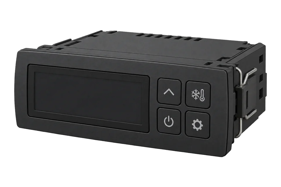
Danfoss ERC 21x
Refrigeration controller
The ERC 211, ERC 213 and ERC 214 are Danfoss's compact controllers for self-contained refrigerated cabinets and similar ventilated units, with one, three or four relays and preset applications AP1 to AP6. Their only data connection is a 4-pin TTL serial port (GND, TX, RX, +5 V), the port the EKA 183B programming key uses. Danfoss publishes Modbus parameter numbers (PNU) for that port: the Sair air probe, the Sdef evaporator probe, the Sc condenser probe, the setpoint, the alarm limits and the relay states. Edge reads them through a TTL to RS-485 interface and a ZMB-31. For a food safety record, a TES-2X probe in the cabinet needs no connection to the controller at all.
Compatibility
Compatible with EpiSensor Edge over Modbus RTU
Danfoss publishes Modbus parameter numbers for the ERC 211, ERC 213 and ERC 214 on their TTL serial port. A TTL to RS-485 interface puts that port on an RS-485 pair, which a ZMB-31 reads and sends to Edge over the EpiSensor wireless network. A TES-2X probe in the cabinet measures the temperature with no connection to the controller.
ERC 211 with software 4.13, ERC 213 and ERC 214 with software 4.16, from Danfoss's ERC 21X Modbus parameter guide. Danfoss's EKA 206 RS-485 adapter lists the EKC 223 and EKC 224 as its supported controllers, so choose a TTL to RS-485 interface that drives the ERC's TTL port and confirm it with the first read. Site check: read Sair (u01) beside the display. The ERC list gives a scale of 0.01 for temperatures where Danfoss's EKC lists give 0.1; keep the multiplier that matches the display. Read-only monitoring.
Connect it with


For setpoint, defrost, relay and alarm data from the controller itself
- Wired
- Edge
- Platforms
For food safety records, or where the controller has no data connection
- Wired
- Edge
- Platforms
Specifications
The ERC 21x family controls one compressor and defrost circuit in a ventilated refrigeration unit. The ERC 211 has one relay, the ERC 213 three (compressor, defrost, fan) and the ERC 214 four, adding an alarm or light relay. Six preset applications set it up for medium and low temperature cabinets with natural, timed electric or temperature-terminated electric defrost.23
- Supply
- 115 V AC or 230 V AC, 50/60 Hz, by product code; less than 0.7 W2
- Sensor types
- NTC 5 kΩ, NTC 10 kΩ, PTC 990 Ω or Pt1000, all of one type, set with o062
- Measuring range
- -40 to 105 °C2
- Controller accuracy
- ±0.5 K from -35 to 25 °C; ±1 K below -35 °C and above 25 °C2
- Data port
- 4-pin TTL serial (GND, TX, RX, +5 V), shared with the EKA 183B programming key2
- Serial address
- o03, 0 to 247 (PNU 2008)1
- Operating conditions
- -10 to 55 °C, 90 % RH2
Interface
This register map is for the ERC 211.
Communication settings: ERC 211
- Protocol
- Modbus RTU over RS-485
- Physical port
- 4-pin TTL serial (GND, TX, RX, +5 V) through a TTL to RS-485 interface
- Unit address
- o03, 0 to 247
- PNU convention
- Register address = Danfoss PNU minus 1
- Temperatures
- Signed 16-bit; Danfoss prints a scale of 0.01, confirm against the display
- Read with
- FC03 (holding registers)
- Addresses
- Zero-based PDU addresses, as sent on the bus
- Route into Edge
- Read Sair at 2529, the regulation reference at 2500 and the compressor relay at 2509 with FC03. Software 4.13 list.
From Programming guide ERC 21X Modbus parameter (DKRCC.EZ.RL0.A1.02 / 520H9702, 2015.02)1.
Register map: ERC 211
| Point | Address | Hex | Format | Scale | Unit |
|---|---|---|---|---|---|
| Sair air temperature (u01) | 2529 | 0x09E1 |
INT16 | ×0.01 | °C |
| Regulation reference (u02) | 2500 | 0x09C4 |
INT16 | ×0.01 | °C |
| Sc condenser temperature | 2646 | 0x0A56 |
INT16 | ×0.01 | °C |
| Setpoint (r00) | 99 | 0x0063 |
INT16 | ×0.01 | °C |
| Differential (r01) | 100 | 0x0064 |
INT16 | ×0.01 | K |
| High alarm limit (A13) | 10018 | 0x2722 |
INT16 | ×0.01 | °C |
| Low alarm limit (A14) | 10019 | 0x2723 |
INT16 | ×0.01 | °C |
| Controller status (u00) | 2006 | 0x07D6 |
UINT16 | ×1 | - |
| DI1 input (u10) | 2001 | 0x07D1 |
UINT16 | ×1 | - |
| Night operation (u13) | 2532 | 0x09E4 |
UINT16 | ×1 | - |
| Compressor relay (u58) | 2509 | 0x09CD |
UINT16 | ×1 | - |
| Main switch (r12) | 116 | 0x0074 |
INT16 | ×1 | - |
This register map applies to the ERC 213 and ERC 214.
Communication settings: ERC 213 and ERC 214
- Protocol
- Modbus RTU over RS-485
- Physical port
- 4-pin TTL serial (GND, TX, RX, +5 V) through a TTL to RS-485 interface
- Unit address
- o03, 0 to 247
- PNU convention
- Register address = Danfoss PNU minus 1
- Temperatures
- Signed 16-bit; Danfoss prints a scale of 0.01, confirm against the display
- Read with
- FC03 (holding registers)
- Addresses
- Zero-based PDU addresses, as sent on the bus
- Route into Edge
- Read Sair at 2529, Sdef at 1010 and the compressor, fan, defrost and alarm relays at 2509 to 2511 and 2582 with FC03. Software 4.16 list.
From Programming guide ERC 21X Modbus parameter (DKRCC.EZ.RL0.A1.02 / 520H9702, 2015.02)1.
Register map: ERC 213 and ERC 214
| Point | Address | Hex | Format | Scale | Unit |
|---|---|---|---|---|---|
| Sair air temperature (u01) | 2529 | 0x09E1 |
INT16 | ×0.01 | °C |
| Sdef evaporator temperature (u09) | 1010 | 0x03F2 |
INT16 | ×0.01 | °C |
| Sc condenser temperature | 2646 | 0x0A56 |
INT16 | ×0.01 | °C |
| Regulation reference (u02) | 2500 | 0x09C4 |
INT16 | ×0.01 | °C |
| Setpoint (r00) | 99 | 0x0063 |
INT16 | ×0.01 | °C |
| Differential (r01) | 100 | 0x0064 |
INT16 | ×0.01 | K |
| High alarm limit (A13) | 10018 | 0x2722 |
INT16 | ×0.01 | °C |
| Low alarm limit (A14) | 10019 | 0x2723 |
INT16 | ×0.01 | °C |
| Controller status (u00) | 2006 | 0x07D6 |
UINT16 | ×1 | - |
| DI1 input (u10) | 2001 | 0x07D1 |
UINT16 | ×1 | - |
| DI2 input (u37) | 2555 | 0x09FB |
UINT16 | ×1 | - |
| Night operation (u13) | 2532 | 0x09E4 |
UINT16 | ×1 | - |
| Compressor relay (u58) | 2509 | 0x09CD |
UINT16 | ×1 | - |
| Fan relay (u59) | 2510 | 0x09CE |
UINT16 | ×1 | - |
| Defrost relay (u60) | 2511 | 0x09CF |
UINT16 | ×1 | - |
| Alarm relay (u62) | 2582 | 0x0A16 |
UINT16 | ×1 | - |
| Light relay (u63, ERC 214) | 2583 | 0x0A17 |
UINT16 | ×1 | - |
| Main switch (r12) | 116 | 0x0074 |
INT16 | ×1 | - |
Assessment
ERC 211 (software 4.13), ERC 213 and ERC 214 (software 4.16) on the TTL serial port
- InteroperabilityLimited
- Danfoss publishes the Modbus parameter numbers, but the only port is TTL and Danfoss names no RS-485 adapter for it in the cited documents.125
- AccuracySupported with conditions
- ±0.5 K from -35 to 25 °C on the controller's own probes, with an EN 13485 class I statement for an AKS 12 sensor. The probe position is set by control, so add an independent probe for product records.2
- SecurityNot yet assessed
- The programming port has a password parameter (o05) for the keypad; nothing in the cited documents protects the serial interface.
- ReliabilitySupported with conditions
- Voltage protection (A72 to A75), a delay of outputs at start-up (o01) and compressor protection on high condenser temperature are documented. Edge should record the controller status beside the temperature.12
- RuggednessSupported with conditions
- Front IP65 with the seal, rear IP00, -10 to 55 °C at 90 % RH, condensate free.23
- ScalabilityLimited
- Addresses 0 to 247 in o03, but every controller needs its own TTL to RS-485 interface on its programming port.12
- LifecycleSupported with conditions
- The parameter list is tied to software 4.13 and 4.16. Keep the software version with each installed controller and repeat the first read after a replacement.1
Edge templates
This JSON file supplies the register map. Applying it to an existing meter replaces its sensor list while retaining the site connection, unit ID and enable state.
Downloads need a signed-in account with Edge download access.
Use the template in Edge
- Import the JSON file
In Edge, open Settings, then Devices and Templates. Choose Import JSON and select the downloaded file. Confirm that the model and template name match your device.
- Load the map for your meter
For a new Modbus device, use Load Template before entering the manufacturer or model; it fills those fields and the register list. Set the name, site connection and unit ID, check the polling enable state, then test before saving. For an existing device, apply only to the matching model; this replaces its sensor list but retains its connection, unit ID and enable state.
- Test a reading
Use Test in the wizard and compare a known reading with the meter display. Check its unit, sign and scale, then confirm that timestamps keep advancing. These starter maps are read-only and leave exports off until you configure them.
Setup
Read the Sair air temperature
Danfoss lists u01 Sair at PNU 2530 on the ERC 211, 213 and 214, read-only, type Float with a scale of 0.01. The register is the PNU minus 1.
- Request PDU
- 03 09 E1 00 01
- Address calculation
- PNU 2530 minus 1 = 2529 = 0x09E1; read one 16-bit register
- Synthetic data example
- 01 F4 = 500: 5.00 °C at scale 0.01, 50.0 °C at scale 0.1
- Acceptance
- Keep the scale that matches the controller display at the same moment
Acceptance: The example bytes are synthetic, not a captured reply. The display settles the scale: a cabinet at 4 °C reads 400 at a scale of 0.01 or 40 at 0.1. Apply the same multiplier to every temperature, setpoint and limit in the template.
-
Connect the TTL port
With the controller off, connect a TTL to RS-485 interface to the 4-pin port (GND, TX, RX, +5 V) and wire its RS-485 pair to the ZMB-31. Keep the TTL lead short and away from the mains and relay wiring.
-
Set the address
Set a unique serial address in o03 (0 to 247; pick 1 or higher). Match the baud rate, parity and stop bits of the interface in the ZMB-31.
-
Read Sair and fix the scale
Read Sair: FC03, register 2529 (PNU 2530), one register, signed 16-bit. Danfoss's ERC list gives a scale of 0.01; compare the result with the display and keep whichever of 0.01 or 0.1 matches it.
-
Import the template for the model
Import the ERC 211 template or the ERC 213 and ERC 214 template, with the multiplier from the first read. Check that the compressor relay and, on the ERC 213 and 214, the defrost relay follow the display icons.
-
Add the independent probe
For the food safety record, place a TES-2X probe at the warmest product position and set its alarm limits and delays from the site's HACCP plan.
Common questions
- Will the EKA 206 RS-485 adapter work on an ERC?
- Danfoss's EKA 206 installation guide lists the EKC 223 and EKC 224 as its supported controllers. Danfoss pairs those with the ERC 213 and ERC 214 in its fact sheet, but does not list the ERC for the EKA 206.45
- Which register holds the cabinet temperature?
- Sair, u01, at PNU 2530: register 2529 with FC03. The ERC 213 and ERC 214 add the Sdef evaporator probe at 1010. The regulation reference u02 at 2500 is the temperature the controller is regulating to at that moment.1
- Is the ERC's own probe enough for HACCP records?
- Danfoss lists HACCP temperature monitoring to EN 13485 class I with an AKS 12 sensor, but the controller probe sits where the controller needs it. Most HACCP plans take the record at the warmest product position. A TES-2X probe there, with the controller's setpoint and relays beside it in Edge, gives both. The food business operator remains responsible for the plan.28
Related devices
Sources
- Programming guide ERC 21X Modbus parameter (DKRCC.EZ.RL0.A1.02 / 520H9702, 2015.02) (opens in a new tab) (PDF)
- Installation guide ERC 213 (DKRCE.PI.RL0.O2.02 / 520H11062, 2016.04) (opens in a new tab) (PDF)
- Installation guide ERC 214 (DKRCE.PI.RL0.N4.02, 2018.10) (opens in a new tab) (PDF)
- Fact sheet: EKC 202x vs EKC 22x, ERC 21x vs EKC 22x (AM446512660651en-000101, 2023.07) (opens in a new tab) (PDF)
- Installation guide RS-485 adapter type EKA 206 (AN433824456218en-000101, 2023.02) (opens in a new tab) (PDF)
- Basic Modbus parameter list, Optyma iCO2 gateway (AU459739305217en-000201): Danfoss PNU and register convention (opens in a new tab) (PDF)
- ZMB-30, ZMB-31, ZMB-33 wireless Modbus interface datasheet (EPI-195-00) (opens in a new tab) (PDF)
- TES-21, TES-22 wireless probe temperature sensor datasheet (EPI-196-00) (opens in a new tab) (PDF)
Further reading
- ApplicationHACCP temperature monitoring
- ApplicationCold room and cold store temperature monitoring
- ApplicationCommercial kitchen energy management
- ApplicationRefrigeration energy monitoring
- ToolModbus register address translator
- ToolModbus data decoder
- GuideDanfoss EKC 202 refrigeration controller
- GuideDanfoss AK-CC55 case and cold room controller
- GuideReading refrigeration controllers over Modbus
- ToolRS-485 termination and bias
- ManufacturerDanfoss devices
- ProtocolModbus devices and register maps
- CategoryRefrigeration controllers
Product names and trademarks belong to their owners. Publication does not imply endorsement or a commercial relationship.