Danfoss EKC 202
Refrigeration controller
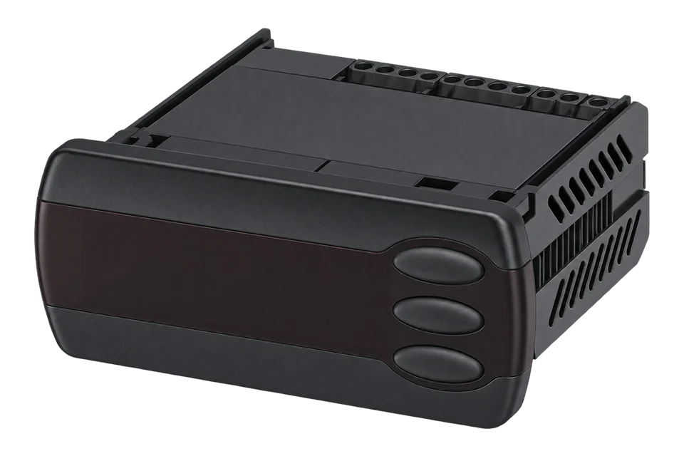
The EKC 202 is Danfoss's panel controller for refrigerated cabinets and cold rooms. It switches the compressor or solenoid valve, defrost, fans and an alarm or light relay from an air probe and an S5 evaporator probe. With the EKA 178A module fitted it answers Modbus RTU on RS-485, and Danfoss publishes a parameter number (PNU) for each reading: the register address is the PNU minus 1, and temperatures are signed tenths of a degree. The EKC 202A, B and C share one list. The EKC 202D adds a second air probe (S3 and S4) and a second digital input, with its own list.
Compatibility
Compatible with EpiSensor Edge over Modbus RTU
With the EKA 178A Modbus module fitted, the EKC 202 answers Modbus RTU on RS-485, which a ZMB-31 reads and sends to Edge over the EpiSensor wireless network. Danfoss publishes the parameter number of every temperature, setpoint, relay and alarm. EpiSensor's Modbus profiles for the EKC 202A and EKC 202D read the same addresses.
EKC 202A, B and C with software 1.3x, and EKC 202D with software 2.2x, each with the EKA 178A module. The EKC 202D1 is a different controller with its own parameter list and is not covered here. Site check: read the display air temperature at register 2575 and compare it with the controller display. Read-only monitoring: setpoints, defrost start, the main switch and the relays are writable parameters and stay out of the templates.
Connect it with


For a cabinet or cold room controller, where a wireless link avoids a data cable back to the Gateway
- Modbus
- Wireless
- Edge
- Platforms
For food safety records, measured at the warmest product position rather than at the controller's own sensor
- Wired
- Edge
- Platforms
Specifications
The EKC 202 controls one refrigerated cabinet or cold room: a refrigeration relay for the compressor or liquid solenoid valve, defrost by time or temperature, evaporator fans and an alarm or light relay. The air probe drives the thermostat and the high and low temperature alarms; the S5 probe on the evaporator ends the defrost. Danfoss's fact sheet maps each EKC 202 model to an EKC 22x counterpart, but the EKC 202 is still common in installed cabinets and cold rooms.15
- Controller role
- Temperature and defrost control for one refrigerated cabinet or cold room1
- Supply
- 230 V AC, 50/60 Hz, 2.0 VA1
- Sensor types
- Pt 1000, PTC 1000 or NTC-M2020 (5000 Ω at 25 °C), selected with o061
- Measuring range
- -60 to +99 °C5
- Relay outputs
- 3 on the EKC 202B; 4 on the EKC 202C and EKC 202D5
- Data communication
- Modbus RS-485 with the EKA 178A module; LON RS-485 with the EKA 179A module5
- Network address
- o03, 0 to 119 on the EKC 202A, B and C; factory setting 01
- Ambient temperature
- 0 to +55 °C1
Interface
This register map applies to the EKC 202A, EKC 202B and EKC 202C.
Communication settings: EKC 202A, B and C
- Protocol
- Modbus RTU over RS-485
- Serial format
- 9600 bit/s, 8 data bits, even parity, 1 stop bit, as in EpiSensor's Modbus profile
- Unit address
- o03, 1 to 119
- PNU convention
- Register address = Danfoss PNU minus 1
- Temperatures
- Signed 16-bit, tenths of a degree
- Read with
- FC03 (holding registers)
- Addresses
- Zero-based PDU addresses, as sent on the bus
- Route into Edge
- Read the display air temperature at 2575, Sair at 2588 and S5 at 1010 with FC03, signed tenths of °C. Software 1.3x parameter list.
From Modbus parameter list, EKC 202C 084B8523, SW 1.3x3.
Register map: EKC 202A, B and C
| Point | Address | Hex | Format | Scale | Unit |
|---|---|---|---|---|---|
| Display air temperature | 2575 | 0x0A0F |
INT16 | ×0.1 | °C |
| Sair air temperature (u69) | 2588 | 0x0A1C |
INT16 | ×0.1 | °C |
| S5 temperature (u09) | 1010 | 0x03F2 |
INT16 | ×0.1 | °C |
| Thermostat reference (u28) | 2545 | 0x09F1 |
INT16 | ×0.1 | °C |
| Cutout setpoint | 99 | 0x0063 |
INT16 | ×0.1 | °C |
| Differential (r01) | 100 | 0x0064 |
INT16 | ×0.1 | K |
| High alarm limit (A13) | 10018 | 0x2722 |
INT16 | ×0.1 | °C |
| Low alarm limit (A14) | 10019 | 0x2723 |
INT16 | ×0.1 | °C |
| Main switch (r12) | 116 | 0x0074 |
INT16 | ×1 | - |
| Controller state | 2006 | 0x07D6 |
UINT16 | ×1 | - |
| Defrost state | 1035 | 0x040B |
UINT16 | ×1 | - |
| DI1 status (u10) | 2001 | 0x07D1 |
UINT16 | ×1 | - |
| Refrigeration relay (u58) | 2509 | 0x09CD |
UINT16 | ×1 | - |
| Fan relay (u59, EKC 202B and C) | 2510 | 0x09CE |
UINT16 | ×1 | - |
| Defrost relay (u60, EKC 202B and C) | 2511 | 0x09CF |
UINT16 | ×1 | - |
| DO4 relay status (u71) | 2590 | 0x0A1E |
UINT16 | ×1 | - |
| Controller error | 2540 | 0x09EC |
UINT16 | ×1 | - |
| Sair sensor error | 20001 | 0x4E21 |
UINT16 | ×1 | - |
| S5 sensor error | 20002 | 0x4E22 |
UINT16 | ×1 | - |
| High temperature alarm | 20003 | 0x4E23 |
UINT16 | ×1 | - |
| Low temperature alarm | 20004 | 0x4E24 |
UINT16 | ×1 | - |
| Door alarm | 20005 | 0x4E25 |
UINT16 | ×1 | - |
| Maximum defrost time alarm | 20008 | 0x4E28 |
UINT16 | ×1 | - |
This register map is for the EKC 202D.
Communication settings: EKC 202D
- Protocol
- Modbus RTU over RS-485
- Serial format
- 9600 bit/s, 8 data bits, even parity, 1 stop bit, as in EpiSensor's Modbus profile
- PNU convention
- Register address = Danfoss PNU minus 1
- Temperatures
- Signed 16-bit, tenths of a degree
- Read with
- FC03 (holding registers)
- Addresses
- Zero-based PDU addresses, as sent on the bus
- Route into Edge
- Read S3 at 2529, S4 at 2530 and S5 at 1010 with FC03, signed tenths of °C. Software 2.2x parameter list.
From Modbus parameters, EKC 202D 084B8536, ver. 2.2x4.
Register map: EKC 202D
| Point | Address | Hex | Format | Scale | Unit |
|---|---|---|---|---|---|
| S3 air temperature (u12) | 2529 | 0x09E1 |
INT16 | ×0.1 | °C |
| S4 air temperature (u16) | 2530 | 0x09E2 |
INT16 | ×0.1 | °C |
| Thermostat air temperature (u17) | 2531 | 0x09E3 |
INT16 | ×0.1 | °C |
| Display air temperature (u56) | 2575 | 0x0A0F |
INT16 | ×0.1 | °C |
| Alarm air temperature (u57) | 2577 | 0x0A11 |
INT16 | ×0.1 | °C |
| S5 evaporator temperature (u09) | 1010 | 0x03F2 |
INT16 | ×0.1 | °C |
| Thermostat reference (u28) | 2545 | 0x09F1 |
INT16 | ×0.1 | °C |
| Cutout setpoint | 99 | 0x0063 |
INT16 | ×0.1 | °C |
| Differential (r01) | 100 | 0x0064 |
INT16 | ×0.1 | K |
| High alarm limit (A13) | 10018 | 0x2722 |
INT16 | ×0.1 | °C |
| Low alarm limit (A14) | 10019 | 0x2723 |
INT16 | ×0.1 | °C |
| Main switch (r12) | 116 | 0x0074 |
INT16 | ×1 | - |
| Controller state | 2006 | 0x07D6 |
UINT16 | ×1 | - |
| Defrost state | 1035 | 0x040B |
UINT16 | ×1 | - |
| DI1 status (u10) | 2001 | 0x07D1 |
UINT16 | ×1 | - |
| DI2 status (u37) | 2555 | 0x09FB |
UINT16 | ×1 | - |
| Refrigeration relay (u58) | 2509 | 0x09CD |
UINT16 | ×1 | - |
| Fan relay (u59) | 2510 | 0x09CE |
UINT16 | ×1 | - |
| Defrost relay (u60) | 2511 | 0x09CF |
UINT16 | ×1 | - |
| Alarm relay (u62) | 2582 | 0x0A16 |
UINT16 | ×1 | - |
| Controller error | 2540 | 0x09EC |
UINT16 | ×1 | - |
| S3 sensor error | 20001 | 0x4E21 |
UINT16 | ×1 | - |
| S4 sensor error | 20002 | 0x4E22 |
UINT16 | ×1 | - |
| S5 sensor error | 20003 | 0x4E23 |
UINT16 | ×1 | - |
| High temperature alarm | 20004 | 0x4E24 |
UINT16 | ×1 | - |
| Low temperature alarm | 20005 | 0x4E25 |
UINT16 | ×1 | - |
| Door alarm | 20006 | 0x4E26 |
UINT16 | ×1 | - |
| Maximum defrost time alarm | 20009 | 0x4E29 |
UINT16 | ×1 | - |
Assessment
EKC 202A, B and C (software 1.3x) and EKC 202D (software 2.2x) with the EKA 178A Modbus module
- InteroperabilitySupported with conditions
- Danfoss publishes a Modbus parameter number for every reading, but the RS-485 port needs the EKA 178A option module.345
- AccuracySupported with conditions
- Air and evaporator temperatures in tenths of a degree from the controller's own probes, which sit where the controller needs them. Food safety records need an independent probe at the product.13
- SecurityNot yet assessed
- Modbus RTU on a local RS-485 bus has no authentication. The cited documents describe an access code for the keypad (o05) but nothing for the bus.
- ReliabilityNot yet assessed
- The instructions list sensor fault codes (E27, E29) and the parameter lists carry a sensor error flag for each probe, which Edge can record beside the temperature.
- RuggednessSupported with conditions
- Operating ambient 0 to +55 °C for a panel-mounted controller. The cited instructions give no enclosure rating.1
- ScalabilitySupported with conditions
- Addresses 1 to 119 on one RS-485 bus. Each controller needs its own address and the model's own template.1
- LifecycleLimited
- Danfoss's fact sheet maps each EKC 202 model to an EKC 22x counterpart. Keep the software version and parameter list with each installed controller.5
Edge templates
This JSON file supplies the register map. Applying it to an existing meter replaces its sensor list while retaining the site connection, unit ID and enable state.
Downloads need a signed-in account with Edge download access.
Use the template in Edge
- Import the JSON file
In Edge, open Settings, then Devices and Templates. Choose Import JSON and select the downloaded file. Confirm that the model and template name match your device.
- Load the map for your meter
For a new Modbus device, use Load Template before entering the manufacturer or model; it fills those fields and the register list. Set the name, site connection and unit ID, check the polling enable state, then test before saving. For an existing device, apply only to the matching model; this replaces its sensor list but retains its connection, unit ID and enable state.
- Test a reading
Use Test in the wizard and compare a known reading with the meter display. Check its unit, sign and scale, then confirm that timestamps keep advancing. These starter maps are read-only and leave exports off until you configure them.
Setup
Read the display air temperature
Danfoss lists the display air temperature at PNU 2576 on the EKC 202B, 202C and 202D, as a one-decimal value. The register is the PNU minus 1.
- Request PDU
- 03 0A 0F 00 01
- Address calculation
- PNU 2576 minus 1 = 2575 = 0x0A0F; read one 16-bit register
- Synthetic data example
- 00 32 = 50, × 0.1 = 5.0 °C; FF CE = -50 signed, × 0.1 = -5.0 °C
- Unit
- °C with r05 Temp. unit (PNU 105) at its factory setting
Acceptance: Compare the decoded value with the controller display at the same moment. The example bytes are synthetic, not a captured reply. If the value is out by a factor of ten or reads a different probe, check the address and the model's list before changing the multiplier.
-
Fit the Modbus module
Switch the controller off and fit the EKA 178A Modbus module. Wire its RS-485 A and B to the ZMB-31 with a twisted pair, kept apart from the mains and relay wiring. Terminate a bus of several controllers at both ends.
-
Set the address and serial format
Set a unique network address in o03; the factory setting is 0, so pick 1 or higher. Set the ZMB-31 to 9600 bit/s, 8 data bits, even parity and 1 stop bit, the format of EpiSensor's EKC 202 Modbus profiles.
-
Read one temperature
Read the display air temperature: FC03, register 2575 (PNU 2576), one register, signed 16-bit, multiplier 0.1. Compare it with the controller display at the same moment.
-
Import the template for the model
Import the EKC 202A, B and C template or the EKC 202D template. The two disagree on the alarm addresses, so do not mix them. Check that the defrost state and the refrigeration relay change when a defrost starts, and that o70 matches the S5 label on the EKC 202A, B and C.
-
Add the independent probe
For the food safety record, place a TES-2X probe at the warmest product position and keep it beside the controller readings in Edge. Set the alarm limits and delays on that probe from the site's HACCP plan.
Common questions
- Which register holds the air temperature?
- On the EKC 202A, B and C, the displayed air temperature is at 2575 (PNU 2576) and the Sair probe itself at 2588 (PNU 2589). On the EKC 202D, S3 is at 2529, S4 at 2530 and the thermostat air value, weighted between them by r15, at 2531. Read all with FC03 as signed tenths of a degree.34
- Is the controller's air temperature enough for HACCP records?
- It is a useful second signal, but the probe sits where the controller needs it, in the evaporator air, and it is there to control. A HACCP record normally wants the temperature at the warmest product position. Add an independent probe there and keep the controller's setpoint, alarms and defrost state beside it to explain an excursion. The food business operator stays responsible for the HACCP plan.18
- Why does the temperature rise every few hours?
- That is usually a defrost. Read the defrost state at 1035 and the defrost relay at 2511 beside the air temperature, and the rise lines up with them. The high temperature alarm has its own delay after a defrost (A12) for the same reason.13
- Can Edge change the setpoint or start a defrost?
- Danfoss lists the cutout setpoint, defrost start and main switch as writable parameters, but this guide and its templates read only. Changing a refrigeration setpoint affects food safety, so it needs the site's own procedure and permission, not a monitoring connection.3
Related devices
Sources
- Instructions EKC 202A, EKC 202B, EKC 202C, RI8JV853, 06-2015 (SW 1.3x) (opens in a new tab) (PDF)
- Parameter identification (Modbus), EKC 202B 084B8522, SW 1.31, RZ8CN102 (opens in a new tab) (PDF)
- Modbus parameter list, EKC 202C 084B8523, SW 1.3x (opens in a new tab) (PDF)
- Modbus parameters, EKC 202D 084B8536, ver. 2.2x (opens in a new tab) (PDF)
- Fact sheet: EKC 202x vs EKC 22x, ERC 21x vs EKC 22x (AM446512660651en-000101, 2023.07) (opens in a new tab) (PDF)
- Basic Modbus parameter list, Optyma iCO2 gateway (AU459739305217en-000201): Danfoss PNU and register convention (opens in a new tab) (PDF)
- ZMB-30, ZMB-31, ZMB-33 wireless Modbus interface datasheet (EPI-195-00) (opens in a new tab) (PDF)
- TES-21, TES-22 wireless probe temperature sensor datasheet (EPI-196-00) (opens in a new tab) (PDF)
Further reading
- ApplicationHACCP temperature monitoring
- ApplicationCold room and cold store temperature monitoring
- ApplicationRefrigeration energy monitoring
- ApplicationSupermarket energy monitoring
- ToolModbus register address translator
- ToolModbus data decoder
- GuideDanfoss AK-CC55 case and cold room controller
- GuideDanfoss ERC 21x refrigeration controller
- GuideReading refrigeration controllers over Modbus
- ToolRS-485 termination and bias
- ManufacturerDanfoss devices
- ProtocolModbus devices and register maps
- CategoryRefrigeration controllers
Product names and trademarks belong to their owners. Publication does not imply endorsement or a commercial relationship.