Eliwell IDNext
Refrigeration controller
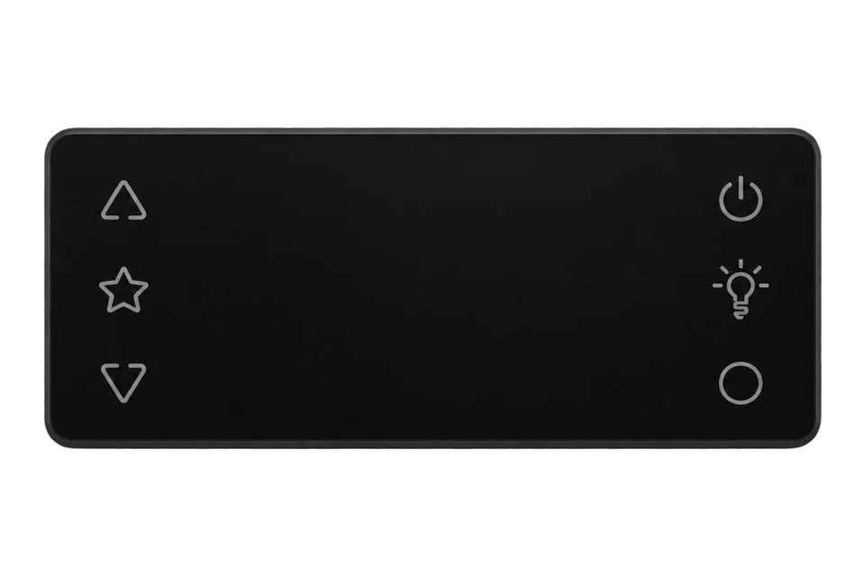
The IDNext -HC is Eliwell's panel controller for refrigerated cabinets and cold rooms, with an 80.5 × 34.5 mm front and support for flammable refrigerants such as R290, from the one-relay IDNext 902 to the four-relay IDNext 978. Its only data connection is a TTL serial port that answers Modbus RTU. An Eliwell BusAdapter converts the port to RS-485, which a ZMB-31 reads. Eliwell's user manual prints a Modbus table: the Pb1 regulation probe at 4109, the Pb2 defrost probe at 4110, the setpoint in use at 4114, and status, alarm and output words with their bit masks. Probe values are signed 16-bit words. The default serial format is address 1, 9600 bit/s and even parity.
Compatibility
Compatible with EpiSensor Edge over Modbus RTU
The IDNext answers Modbus RTU on its TTL serial port. An Eliwell BusAdapter 150 DONGLE, which lists every IDNext model, or a DIN-rail BusAdapter 130 or 150 converts the port to RS-485, and a ZMB-31 reads it and sends it to Edge over the EpiSensor wireless network. Eliwell's user manual prints the Modbus address, size and sign of every probe, status, alarm and counter.
IDNext -HC 902, 961, 971, 974 and 978, with the Modbus tables of user manual IDNXP-02EN (02/2023). The IDPlus and EWPlus have their own tables and are not covered. Site check: read Pb1 at 4109 and compare it with the display. The manual gives the probe range to one decimal place without stating the scale, so the template reads tenths of a degree; correct the multiplier if the first read disagrees. Read-only monitoring: the manual's write commands for outputs, defrost and stand-by are not used.
Connect it with


For probe temperatures, setpoint, defrost, door and alarm data from the controller
- Wired
- Edge
- Platforms
For food safety records, or where no BusAdapter can be fitted
- Wired
- Edge
- Platforms
Specifications
The IDNext -HC family runs a refrigerated cabinet or cold room from one regulation probe (Pb1) and, on the 971, 974 and 978, a defrost probe (Pb2) on the evaporator. The relays range from one compressor relay on the 902 and 961 to compressor, defrost, fan and alarm relays on the 978. It is built for refrigerants including flammable ones, and preset applications AP1 to AP3 load typical settings.1
- Models
- IDNext 902 P, 961 P, 971 P/B, 974 P/B, 974 P/C, 974 P/CI, 978 P/B, 978 P/C, 978 P/CI1
- Supply
- 12 V AC/DC (SELV, Class 2) or 230 V AC ±10 %, 50/60 Hz, by model1
- Probe inputs
- NTC, PTC or Pt1000; Pb1 on every model, Pb2 on the 971, 974 and 9781
- Accuracy
- NTC better than ±1.6 °C ±1 digit from -30 to 110 °C; Pt1000 better than ±2.3 °C ±1 digit; resolution 0.1 °C1
- Modbus functions
- 03 read, 16 write, 43 read device ID; messages up to 50 bytes1
- Serial settings
- Adr 1 to 247 (default 1); bAU 9600, 19200 or 38400 bit/s (default 9600); Pty none, even or odd (default even)1
- RS-485 interface
- BusAdapter 150 DONGLE: A+, B-, GND; 800 m at 9600 bit/s, 400 m at 19200 bit/s; at most 8 unit loads4
- Front protection
- IP65, front panel only1
Interface
This register map applies to the IDNext 902, 961, 971, 974 and 978. IDPlus has its own interface and is not covered here.
Communication settings
- Protocol
- Modbus RTU (Eliwell MSK 750) on the TTL port, through a BusAdapter to RS-485
- Serial format
- Adr 1, bAU 9600 bit/s, Pty E (even parity, 1 stop bit) by default
- Message length
- Up to 50 bytes per request or reply
- Manual addresses
- Used as printed in the Modbus tables, no offset
- Temperatures
- Signed 16-bit (CPL), assumed tenths of a degree
- Read with
- FC03 (holding registers)
- Addresses
- Zero-based PDU addresses, as sent on the bus
- Route into Edge
- Read Pb1 at 4109, Pb2 at 4110, the setpoint in use at 4114 and the status and alarm words at 4115 and 4121 with FC03.
From IDNext -HC user manual (IDNXP-02EN, edition 02, 02/2023), section Modbus MSK 750 functions and resources1.
Register map
| Point | Address | Hex | Format | Scale | Unit |
|---|---|---|---|---|---|
| Pb1 regulation probe (AI1) | 4109 | 0x100D |
INT16 | ×0.1 | °C |
| Pb2 defrost probe (AI2) | 4110 | 0x100E |
INT16 | ×0.1 | °C |
| Pb3 probe (AI3) | 4111 | 0x100F |
INT16 | ×0.1 | °C |
| Setpoint in use (SET) | 4114 | 0x1012 |
INT16 | ×0.1 | °C |
| Setpoint parameter (SEt) | 32769 | 0x8001 |
INT16 | ×0.1 | °C |
| Differential (diF) | 32770 | 0x8002 |
INT16 | ×0.1 | K |
| Maximum alarm threshold (HAL) | 32779 | 0x800B |
INT16 | ×0.1 | °C |
| Minimum alarm threshold (LAL) | 32781 | 0x800D |
INT16 | ×0.1 | °C |
| Status word (stand-by, compressor, defrost, fans, door) | 4115 | 0x1013 |
UINT16 | ×1 | - |
| Digital inputs word (DI1, DI2) | 4118 | 0x1016 |
UINT16 | ×1 | - |
| Outputs word (RL1 to RL4) | 4120 | 0x1018 |
UINT16 | ×1 | - |
| Alarm word (probe faults, door, AL1, AH1) | 4121 | 0x1019 |
UINT16 | ×1 | - |
| Compressor 1 runtime | 4171 | 0x104B |
UINT16 | ×0.1 | h |
| Compressor 1 starts | 4172 | 0x104C |
UINT16 | ×1 | - |
| Defrost 1 time | 4173 | 0x104D |
UINT16 | ×1 | min |
| Defrost 1 count | 4175 | 0x104F |
UINT16 | ×1 | - |
| Door open time | 4176 | 0x1050 |
UINT16 | ×1 | min |
| Door openings | 4177 | 0x1051 |
UINT16 | ×1 | - |
Assessment
IDNext -HC 902, 961, 971, 974 and 978 through a BusAdapter on the TTL port, with the tables of user manual IDNXP-02EN
- InteroperabilitySupported with conditions
- Modbus RTU with a complete published address table, but on a TTL port that needs an Eliwell BusAdapter for RS-485.13
- AccuracyLimited
- Controller accuracy better than ±1.6 °C with NTC and ±2.3 °C with Pt1000, and the scale of the probe registers is not stated. Use the controller for diagnosis and an independent probe for product records.1
- SecurityNot yet assessed
- Parameters have visibility levels for the keypad; the manual describes no protection for the serial interface, which accepts writes and broadcasts.
- ReliabilitySupported with conditions
- Probe faults (E1, E2), defrost timeouts and a clock error are flagged in the alarm word, and the compressor runs a set duty cycle (Ont, OFt) on a failed probe. Record the alarm word beside the temperatures.1
- RuggednessSupported with conditions
- IP65 on the front panel only; the TTL cable is limited to 1 m and the BusAdapter must be fixed inside the equipment.14
- ScalabilitySupported with conditions
- Addresses 1 to 247 and an RS-485 run of 800 m at 9600 bit/s, but each controller needs its own BusAdapter and the bus is limited to 8 unit loads.14
- LifecycleSupported with conditions
- The Modbus table is in an edition-numbered user manual. Keep the manual edition and the controller part number with each installation.1
Edge template
This JSON file supplies the register map. Applying it to an existing meter replaces its sensor list while retaining the site connection, unit ID and enable state.
| Model | Connection | Points | Version | Updated | Download |
|---|---|---|---|---|---|
| IDNext | TTL serial port, Modbus RTU through a BusAdapter, Pb1 on every model, Pb2 on the 971, 974 and 978 | 18 | 1.0.0 | Download |
Downloads need a signed-in account with Edge download access.
Use the template in Edge
- Import the JSON file
In Edge, open Settings, then Devices and Templates. Choose Import JSON and select the downloaded file. Confirm that the model and template name match your device.
- Load the map for your meter
For a new Modbus device, use Load Template before entering the manufacturer or model; it fills those fields and the register list. Set the name, site connection and unit ID, check the polling enable state, then test before saving. For an existing device, apply only to the matching model; this replaces its sensor list but retains its connection, unit ID and enable state.
- Test a reading
Use Test in the wizard and compare a known reading with the meter display. Check its unit, sign and scale, then confirm that timestamps keep advancing. These starter maps are read-only and leave exports off until you configure them.
Setup
Read the Pb1 regulation probe
Eliwell's Modbus resource table lists AI1, the regulation probe, at address 4109: read-only, one word, signed (CPL), range -67.0 to 320.
- Request PDU
- 03 10 0D 00 01
- Address
- 4109 = 0x100D, used as printed; read one 16-bit register
- Synthetic data example
- 00 1E = 30, × 0.1 = 3.0 °C; FF 38 = 65336 - 65536 = -200, × 0.1 = -20.0 °C
- Sign conversion
- 0 to 32767 as read; 32768 to 65535 minus 65536 (the manual's CPL rule)
Acceptance: The example bytes are synthetic, not a captured reply. The manual does not state the scale; compare the decoded value with the display at the same moment and keep the multiplier that matches. A value off by one register usually means the client added 1 to the address.
-
Fit the BusAdapter
With the controller off, plug the BusAdapter 150 DONGLE (or a DIN-rail BusAdapter 130 or 150) into the TTL port with the cable supplied for it. Fix the adapter inside the equipment so it cannot pull out, and wire A+, B- and GND to the ZMB-31.
-
Check the serial settings
In the Add folder, give each controller a unique Adr (1 to 247), keep bAU at 9600 bit/s and note Pty: even parity with 1 stop bit by default. Set the same frame in the ZMB-31. Switch the controller off and on after changing Pty.
-
Read Pb1
Read Pb1: FC03, address 4109, one register, signed 16-bit. Compare it with the display: with the template's multiplier of 0.1, a raw 30 is 3.0 °C. If the display uses °F (dro), the value is in °F.
-
Import the template
Import the IDNext template. Check that bit 4 of the status word (4115) sets during a defrost and bit 15 when the door opens, and read Att, HAL and LAL before relying on the controller's alarm bits.
-
Add the independent probe
For the food safety record, place a TES-2X probe at the warmest product position and set its alarm limits and delays from the site's HACCP plan.
Common questions
- Does the IDNext have Modbus?
- Yes, on its TTL serial port. Eliwell's user manual documents Modbus RTU with function 03 to read, 16 to write and 43 to read the device ID, and prints the address of every resource. RS-485 needs an Eliwell BusAdapter between the port and the ZMB-31.12
- Which BusAdapter do I need?
- The BusAdapter 150 DONGLE (BA00000XD00x) lists every IDNext part number as a supported device; it is not opto-isolated. The DIN-rail BusAdapter 130 and 150 are opto-isolated, and the 150 has reinforced insulation. Eliwell's own instruction is to check the controller's documentation for the adapter model.135
- Where are the door and defrost states?
- In the status word at 4115: bit 4 (mask 16) is defrost 1 and bit 15 (mask 32768) the door status. The door-open alarm is bit 3 (mask 8) of the alarm word at 4121. Edge reads each word whole; decode the bit in Edge or the receiving platform.1
- Can I use the IDNext addresses on an IDPlus?
- No. The IDPlus selects Televis or Modbus with PtS and has its own Modbus table; the IDNext table in this guide does not apply to it. The BusAdapter 150 DONGLE lists IDPlus models too, so the wiring is the same.36
- Is the controller probe enough for HACCP records?
- Eliwell states better than ±1.6 °C for an NTC probe on the controller, and the probe sits where the controller needs it. Most HACCP plans take the record at the warmest product position with a tighter probe, such as a TES-2X at ±0.2 °C in its normal range, and keep the controller data beside it. The food business operator remains responsible for the plan.18
Related devices
Sources
- IDNext -HC user manual (IDNXP-02EN, edition 02, 02/2023), section Modbus MSK 750 functions and resources (opens in a new tab)
- IDNext 974 P NTC 2Hp/8/5 12Vac/dc BUZ AIR -HC (IDN974PED303000) product page (opens in a new tab)
- BusAdapter 150 DONGLE (BA00000XD00x): list of supported devices (9IS64572.01, 03-2023) (opens in a new tab)
- BusAdapter 150 DONGLE instruction sheet (9IS64560.01, 11-2021) (opens in a new tab)
- BusAdapter 130-150, TTL-RS 485 serial interface on DIN rail, instruction sheet (9IS43084, 11-14) (opens in a new tab)
- IDPlus 961-974 -HC instruction sheet (9IS54671.00, 10-18) (opens in a new tab)
- ZMB-30, ZMB-31, ZMB-33 wireless Modbus interface datasheet (EPI-195-00) (opens in a new tab) (PDF)
- TES-21, TES-22 wireless probe temperature sensor datasheet (EPI-196-00) (opens in a new tab) (PDF)
Further reading
- ApplicationHACCP temperature monitoring
- ApplicationCold room and cold store temperature monitoring
- ApplicationCommercial kitchen energy management
- ApplicationSupermarket energy monitoring
- ToolModbus register address translator
- ToolModbus data decoder
- GuideDanfoss AK-CC55 case and cold room controller
- GuideDanfoss ERC 21x refrigeration controller
- GuideReading refrigeration controllers over Modbus
- ToolRS-485 termination and bias
- ProtocolModbus devices and register maps
- CategoryRefrigeration controllers
Product names and trademarks belong to their owners. Publication does not imply endorsement or a commercial relationship.