Dixell XR77CX
Refrigeration controller
The Dixell XR77CX controls the compressor, fan, defrost and light of a low temperature cabinet or cold room, with an optional clock for scheduled defrosts. Its built-in RS485 line makes it compatible with EpiSensor Edge over Modbus RTU through a ZMB Modbus interface, with no converter. EpiSensor's Modbus profile reads the room probe, setpoint and differential.
Compatibility
Compatible with EpiSensor Edge over Modbus RTU through a ZMB Modbus interface
Dixell documents a built-in RS485 serial line on the XR77CX for a Modbus RTU monitoring system, with the address set by parameter Adr. A ZMB-31 or ZMB-30 on that line reads the controller and sends the values to the Gateway running Edge. The addresses come from EpiSensor's Modbus profile for the XR77CX.
Set Adr to a unique address first. Dixell's manual prints no register table, so compare the room probe with the display once, and record the parameter table code the controller reports as Ptb. Setpoint and parameter writes stay with the refrigeration contractor.
Connect it with


For any XR77CX: the RS485 line is on the controller's own terminals
- Modbus
- Wireless
- Edge
- Platforms
Specifications
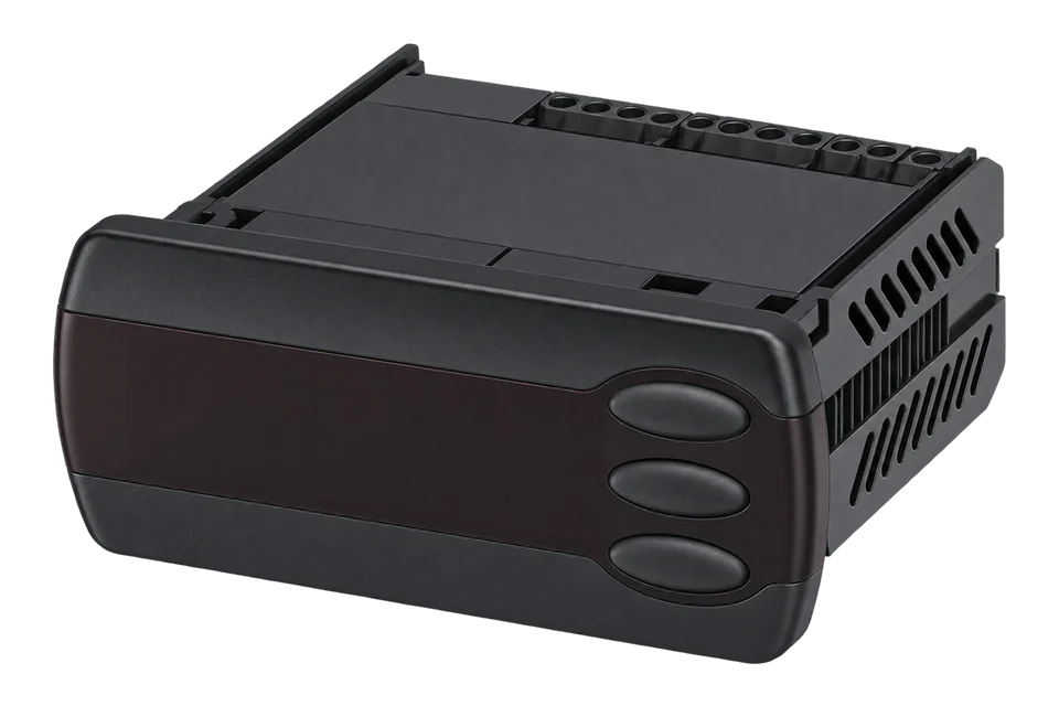
Dixell's manual describes the XR77CX as a 32 x 74 mm microprocessor controller for low temperature ventilated refrigerating units with four relays, an optional real time clock with up to six daily defrosts split into workdays and holidays, and a day and night function with two setpoints.1
- Power supply
- 24 Vac ±10 %, 12 to 40 Vdc ±10 %, 110 Vac or 230 Vac, 50/60 Hz, by model; 3 VA max1
- Probe inputs
- Up to 4 NTC or PT1000 probes, set by PbC1
- Measuring range
- NTC -40 to 110 °C; PT1000 -100 to 150 °C1
- Accuracy and resolution
- ±0.7 °C ±1 digit at 25 °C ambient; 0.1 °C, 1 °C or 1 °F selectable1
- Relay outputs
- Compressor SPST 8(3) A or 16 A; defrost SPDT 8(3) A; fan SPST 5 A; aux SPDT 8(3) A, 250 Vac1
- Serial line
- Built-in RS485 for Modbus RTU; address Adr 1 to 247, default 11
- Housing and protection
- 32 x 74 mm front, 60 mm deep, 71 x 29 mm panel cut-out; IP20, IP65 front1
- Operating conditions
- 0 to 55 °C, 20 to 85 % RH non-condensing; clock back-up 24 hours1
Interface
This register map is for the XR77CX. XR75CX has its own interface and is not covered here.
Communication settings
- Protocol
- Modbus RTU on the built-in RS485 terminals (16 +, 17 -)
- Unit address
- Parameter Adr, 1 to 247, default 1
- Baud rate
- 9600 bit/s
- Data bits, parity and stop bits
- 8 data bits, no parity, 1 stop bit
- Read with
- FC03 (holding registers)
- Addresses
- Zero-based PDU addresses, as sent on the bus
- Route into Edge
- ZMB-31 or ZMB-30 on the RS485 terminals at 9600 bit/s 8N1. Any ZMB reads the three starter points; the ZMB-30 also adds its own waterproof probe.
From EpiSensor Modbus profile for the Dixell XR77CX4.
Register map
| Point | Address | Hex | Format | Scale | Unit |
|---|---|---|---|---|---|
| Room probe P1 | 256 | 0x0100 |
INT16 | ×0.1 | °C |
| Differential Hy | 769 | 0x0301 |
UINT16 | ×0.1 | °C |
| Setpoint | 882 | 0x0372 |
INT16 | ×0.1 | °C |
Assessment
XR77CX on its built-in RS485 line, read with EpiSensor's Modbus profile. Relay, alarm, door and clock states are outside this starter map.
- InteroperabilitySupported with conditions
- Dixell documents Modbus RTU on built-in RS485. The register addresses come from EpiSensor's profile, not a published Dixell table, and depend on the map code.14
- AccuracySupported with conditions
- Dixell states ±0.7 °C ±1 digit and 0.1 °C resolution with NTC or PT1000 probes. The room probe is placed for control.1
- SecurityNot yet assessed
- The manual describes a keyboard lock but no protection on the serial line.1
- ReliabilitySupported with conditions
- The RS485 line is on the controller's own terminals, and the manual lists probe failure and clock alarms. Edge timestamps each read, so a lost bus shows as missing data.1
- RuggednessSupported with conditions
- IP65 front and IP20 body, rated 0 to 55 °C.1
- ScalabilityWell supported
- Built-in RS485 with addresses from 1 to 247 lets several controllers share one bus without converters.1
Edge template
This JSON file supplies the register map. Applying it to an existing meter replaces its sensor list while retaining the site connection, unit ID and enable state.
| Model | Connection | Points | Version | Updated | Download |
|---|---|---|---|---|---|
| XR77CX | Built-in RS485, Modbus RTU, address Adr, 1 to 247, default 1 | 3 | 1.0.0 | Download |
Downloads need a signed-in account with Edge download access.
Use the template in Edge
- Import the JSON file
In Edge, open Settings, then Devices and Templates. Choose Import JSON and select the downloaded file. Confirm that the model and template name match your device.
- Load the map for your meter
For a new Modbus device, use Load Template before entering the manufacturer or model; it fills those fields and the register list. Set the name, site connection and unit ID, check the polling enable state, then test before saving. For an existing device, apply only to the matching model; this replaces its sensor list but retains its connection, unit ID and enable state.
- Test a reading
Use Test in the wizard and compare a known reading with the meter display. Check its unit, sign and scale, then confirm that timestamps keep advancing. These starter maps are read-only and leave exports off until you configure them.
Setup
Read the room probe
EpiSensor's Modbus profile places the XR77CX room probe at holding register 256 (0x0100) as a signed value in tenths of a degree.
- Request PDU
- 03 01 00 00 01
- Address
- 256 decimal = 0x0100, zero-based, one register
- Decode
- Signed 16-bit, divide by 10 with rES = dE: a synthetic reply of FF 06 is -250, which is -25.0 °C
- Compare with
- The XR77CX display, which shows the room probe by default
Acceptance: Accept the map when the room probe agrees with the display. The reply bytes are an example, not a captured reply. If nothing answers, check Adr, the + and - polarity and 9600 bit/s.
-
Set the address
Set Adr (1 to 247) to a unique address for the bus and note Ptb, the parameter map code. Check rES: the tenths decode applies with rES = dE in °C.
-
Wire the RS485 terminals to the ZMB
Connect the controller's RS485 + and - to the ZMB with shielded twisted pair, terminate both ends, and set the ZMB to 9600 bit/s, 8 data bits, no parity, 1 stop bit.
-
Read the room probe once
Read holding register 256 (0x0100) with FC03 and divide by 10. Compare it with the display.
-
Add the setpoint and differential
Read the setpoint at 882 (0x0372) and Hy at 769 (0x0301). If the setpoint does not match SEt on the controller, leave it out and confirm the map for the reported Ptb.
-
Place the record probe
Fit an independent probe at the warmest product position and set Edge alarm limits and delays to the site's HACCP plan.
Common questions
- Does the XR77CX need a converter for Modbus?
- No. The XR77CX has a built-in RS485 line for a Modbus RTU monitoring system. Wire it straight to the ZMB.1
- Where do the register addresses come from?
- From EpiSensor's Modbus profile for the XR77CX. Dixell's manual prints no register table, so compare the room probe with the display before saving the map.14
- Why might the setpoint read a different value?
- Dixell's manual lists Ptb, a read-only parameter map code, and the parameter registers follow that map. Record Ptb and compare the setpoint read with SEt on the controller before keeping it.1
Related devices
Sources
- XR77CX installing and operating instructions 1592020620 r1.0, 23.03.2015 (opens in a new tab) (PDF)
- XR75CX installing and operating instructions 1592020610 r1.0, 27.03.2015 (opens in a new tab) (PDF)
- Dixell brand page (opens in a new tab)
- EpiSensor Modbus profile for the Dixell XR77CX (opens in a new tab)
- ZMB-3X Modbus interface datasheet EPI-195-00 (opens in a new tab) (PDF)
Further reading
- ApplicationHACCP temperature monitoring
- ApplicationCold chain temperature monitoring
- ApplicationRefrigeration energy monitoring
- ApplicationSupermarket energy monitoring
- ToolModbus register address converter
- ToolModbus data decoder
- GuideReading refrigeration controllers over Modbus
- GuideModbus commissioning over RS-485
- GuideDixell XR60CX
- GuideDixell XR170C
- ManufacturerDixell devices
- ProtocolModbus devices and register maps
- CategoryRefrigeration controllers
Product names and trademarks belong to their owners. Publication does not imply endorsement or a commercial relationship.