Danfoss Icon2
Underfloor heating controller
Danfoss Icon2 controls hydronic underfloor heating room by room. Its Main Controller drives up to 15 actuator outputs from wired or wireless room thermostats, and joins a Zigbee 3.0 network so Edge can read and set every room through one device.
Also sold asDanfoss Icon2 Main Controller
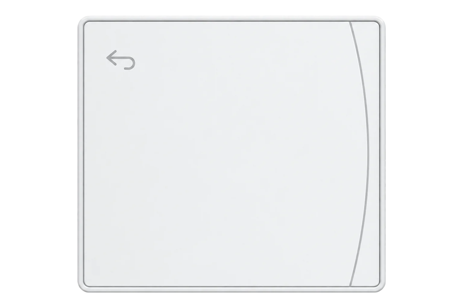
- Zigbee
Underfloor heating controller
Compatibility
Compatible with EpiSensor Edge over Zigbee.
Pair it with the Zigbee radio on an EpiSensor Gateway. Edge reads it locally on the Gateway.
Edge reads 24 values from it, listed under Interface.
Connect it with
-
Gateway ZGW-20From €899 ex VAT Configure Gateway

Specifications
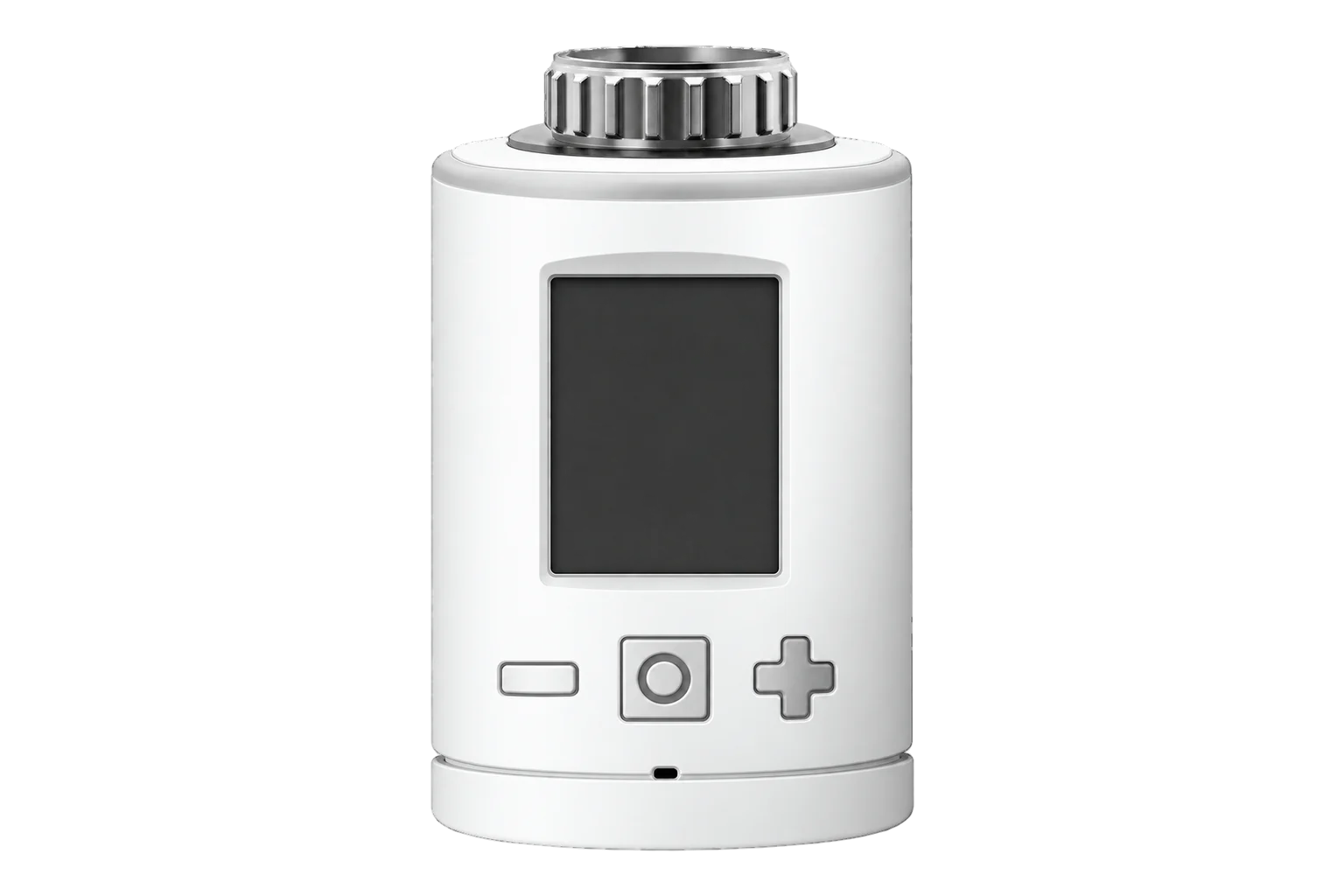
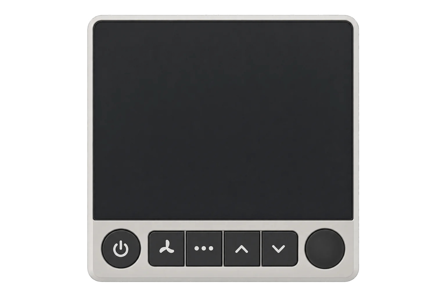
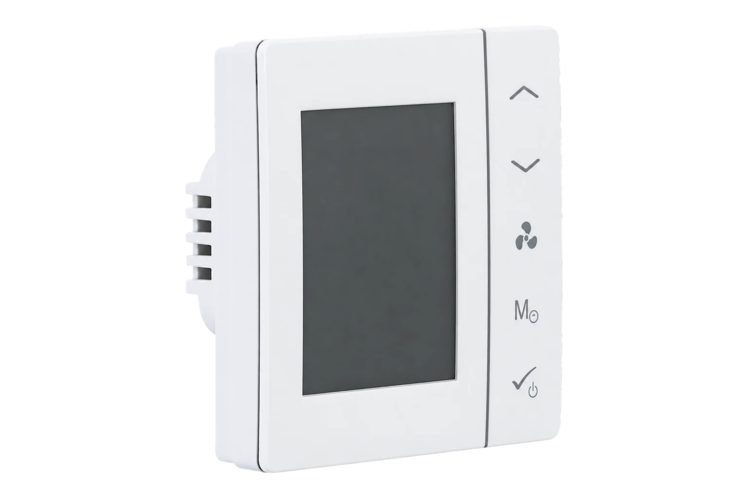
Icon2 is Danfoss’s room control system for hydronic floor heating and other systems with thermal actuators. The Main Controller sits at the manifold and switches one 230 V thermal actuator per output; the Advanced Main Controller has 15 outputs, and a conversion module changes them to 24 V. Room thermostats connect to it by wire or wirelessly. Danfoss makes display thermostats, a version with an infrared floor sensor, in-wall and on-wall thermostats, and a sensor with no display.1
- Power
- Mains. The Main Controller runs from 220 to 240 V AC and must be earthed. Wireless room thermostats and the Icon2 Sensor run on 1.5 V AAA alkaline cells.1
- Advanced Main Controller
- 088U2110, 15 actuator outputs1
- Actuator outputs
- 230 V thermal actuators, one per output; 24 V with conversion module 088U21401
- Mains supply
- 220 to 240 V AC, 50/60 Hz1
- Plant outputs
- Pump output PWR1 (230 V, max. 100 W) and a voltage-free relay for heat demand1
- Supply sensor input
- PT1000, for flow temperature control1
- Rooms over Zigbee
- Up to 15, one endpoint each3
- Setpoint range
- 5 to 35 °C per room, 0.5 °C steps3
- Floor temperature limits
- 18 to 35 °C3
- Controllers per system
- Up to four Main Controllers, wirelessly linked1
- Wireless thermostat batteries
- 1.5 V AAA alkaline1
- Range accessories
- Zigbee repeater 088U1131, external antenna 088U21411
Where it is used
Room temperature and setpoints across a floor-heated office, school or care home, read through one controller per manifold.
Indoor environmental monitoringMatching heat demand from the floor heating to a heat pump’s electricity and heat output, using the controller’s heat supply request.
Heat pump performance monitoringAlarming on floor sensor faults, lost thermostats and supply sensor faults from the room and system status codes.
Interface
Readings and settings, with units and ranges where Danfoss publishes them. readable, readable and writable.3
| Reading | Unit | Range or values | Access |
|---|---|---|---|
| Measurements 7 | |||
| Room temperaturePer room: N is the room number, 1 to 15. | °C | - | Read only |
| Floor temperaturePer room: N is the room number, 1 to 15. | °C | - | Read only |
| HumidityPer room: N is the room number, 1 to 15. | % | - | Read only |
| Heating statePer room: N is the room number, 1 to 15. | - | idleheat |
Read only |
| Actuator outputPer room: N is the room number, 1 to 15. | - | inactiveactive |
Read only |
| Heat supply requestMain Controller: whether any room needs heat from the plant. | - | noneheat_supply_request |
Read only |
| Water in the pipesMain Controller: heating or cooling water. | - | hot_water_flow_in_pipescool_water_flow_in_pipes |
Read only |
| Controls 2 | |||
| Heating setpointPer room: N is the room number, 1 to 15. | °C | 5 to 35 °C | Read and write |
| System modePer room: N is the room number, 1 to 15. | - | heat |
Read and write |
| Settings 9 | |||
| Lowest setpoint allowedPer room: N is the room number, 1 to 15. | °C | 4 to 35 °C | Read and write |
| Highest setpoint allowedPer room: N is the room number, 1 to 15. | °C | 4 to 35 °C | Read and write |
| Minimum floor temperaturePer room: N is the room number, 1 to 15. | °C | 18 to 35 °C | Read and write |
| Maximum floor temperaturePer room: N is the room number, 1 to 15. | °C | 18 to 35 °C | Read and write |
| Floor sensor modePer room: N is the room number, 1 to 15. | - | comfortfloor_onlydual_mode |
Read only |
| Schedule in usePer room: N is the room number, 1 to 15. | - | regular_schedule_selectedvacation_schedule_selected |
Read only |
| Pre-heatPer room: N is the room number, 1 to 15. | - | disableenable |
Read only |
| ApplicationMain Controller: the Icon2 application number set at commissioning. | - | 01234567and 13 more |
Read only |
| Forced heating or coolingMain Controller. | - | force_heatingforce_coolingnone |
Read only |
| Diagnostics 6 | |||
| Pre-heat statusPer room: N is the room number, 1 to 15. | - | disableenable |
Read only |
| Setpoint change sourcePer room: N is the room number, 1 to 15. | - | manualscheduleexternally |
Read only |
| Room statusPer room: N is the room number, 1 to 15. | - | no_errormissing_rtrt_touch_errorfloor_sensor_short_circuitfloor_sensor_disconnected |
Read only |
| Thermostat batteryPer room: N is the room number, 1 to 15. | % | 0 to 100 % | Read only |
| Main Controller statusMain Controller. | - | no_errormissing_expansion_boardmissing_radio_modulemissing_command_modulemissing_master_railmissing_slave_rail_no_1missing_slave_rail_no_2pt1000_input_short_circuitand 2 more |
Read only |
| Controller roleMain Controller: its role when several controllers work together. | - | invalid_unusedmasterslave_1slave_2 |
Read only |
Every room property carries its room number as a suffix, for example local_temperature_3 for room 3.3
System properties carry the suffix 232, the Main Controller’s own endpoint: heat_supply_request_232, system_status_water_232 and system_status_code_232.3
temperature_N is the floor temperature and needs a floor sensor on that room’s thermostat. local_temperature_N is the air temperature.3
Commission the room thermostats before joining. Danfoss’s controller refuses to join the Ally Gateway while no room thermostats are connected to it.1
Setup
-
Commission the Icon2 system first
Connect the actuators, thermostats and accessories, then power up the Main Controller and link each thermostat to its outputs with the Icon2 app over Bluetooth or on the controller itself.1
-
Open pairing in Edge
Open pairing on the Gateway’s Zigbee network in Edge. A Zigbee 3.0 network needs the QR code in the lower left corner of the Main Controller’s front, which carries its install code.1
-
Press OK on the Main Controller
Press the OK button on the Main Controller to finish joining. It then sends its rooms to the network.1
-
Check every room
Confirm that Edge identifies it as Danfoss Icon2, then check that each commissioned room reports a room temperature. Change one room’s setpoint from Edge and confirm it on that room’s thermostat.
Common questions
- Which part of Icon2 pairs with the Gateway?
- The Main Controller. It joins the Zigbee network and brings every room linked to it, up to 15, as numbered endpoints. The room thermostats stay linked to the controller.13
- Do I need the Danfoss Ally Gateway?
- No. Danfoss documents joining Icon2 to other Zigbee-based systems: scan the QR code on the Main Controller for a Zigbee 3.0 network, then press OK. The Ally Gateway is only needed for the Danfoss Ally app.1
- Can Edge read floor temperature?
- Yes, for rooms whose thermostat has a floor sensor, either the optional wired sensor or the Featured thermostat’s infrared sensor. It appears as temperature_N beside the air temperature local_temperature_N.13
- How do I remove it from an old Zigbee network?
- Hold the > button for 15 seconds and release when the left LED blinks. Both LEDs turn red while the outputs light in sequence; when the left LED is off and the right is green, the controller has left the network.1
- The controller sits in a metal cabinet. Will it reach the Gateway?
- Metal blocks the signal. Danfoss sells an external antenna for the Main Controller for this case, and a Zigbee repeater to extend range to the thermostats.1
Related devices
More from Danfoss

Sources
- Danfoss Icon2 application guide (opens in a new tab) (PDF)
- Danfoss Icon2 (opens in a new tab)
- Danfoss Icon2 Zigbee definition (opens in a new tab)
- Danfoss Icon2 device documentation (opens in a new tab)
Further reading
Product names and trademarks belong to their owners. Publication does not imply endorsement or a commercial relationship.