Carlo Gavazzi WM20 / WM30 / WM40
Panel-mounted power analyser
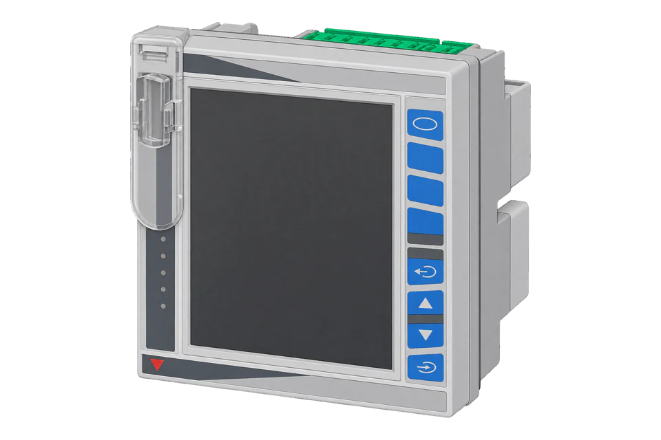
The WM20, WM30 and WM40 are modular three-phase power analysers for a 96 x 96 mm panel cut-out, measuring through external 1 A or 5 A current transformers. None has a communication port of its own: the port comes from a plug-in module, MC485232 for RS-485 Modbus RTU, MCETH for Modbus TCP or MCBACIP for BACnet/IP and Modbus TCP. Carlo Gavazzi publishes one communication protocol for all three. Instantaneous values are IEEE 754 floats with the low word in the first register, so V L1-N at 0050h needs a word-swapped decode. Energy counters are 64-bit integers in Wh, which Edge's Modbus client does not read.
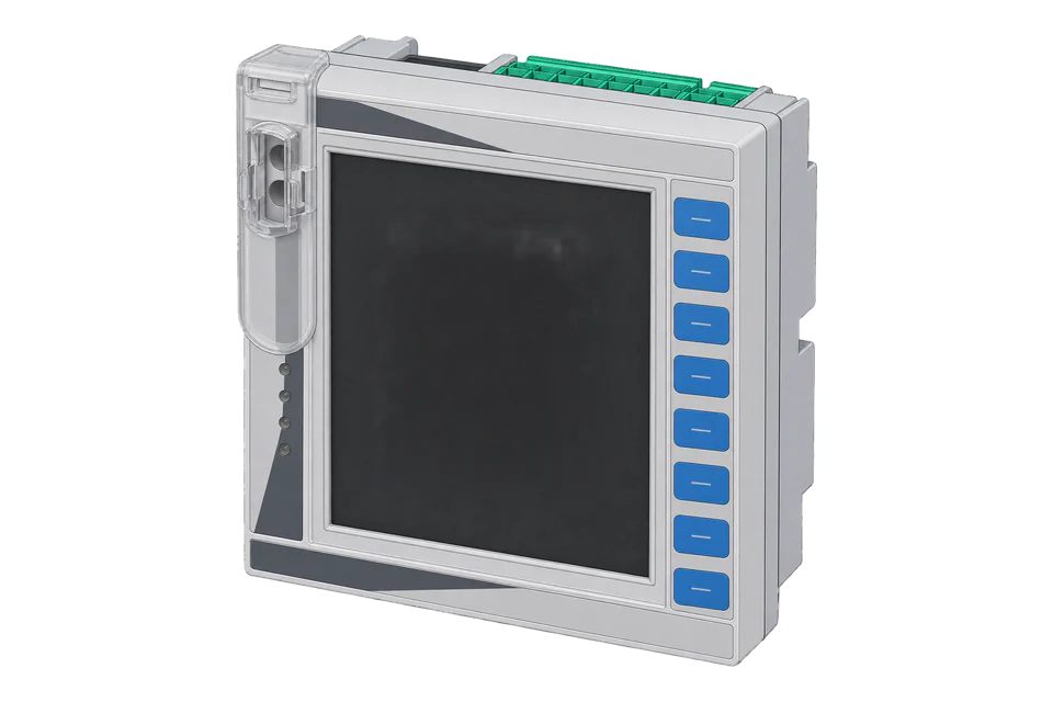
Compatibility
Compatible with EpiSensor Edge over Modbus RTU, Modbus TCP or BACnet/IP
The WM20, WM30 and WM40 are compatible with EpiSensor Edge through their plug-in communication module: Modbus RTU on the MC485232 RS-485 port, read through a ZMB-31 Modbus Interface or a Gateway serial port, Modbus TCP on the MCETH or MCBACIP Ethernet port, and BACnet/IP on the MCBACIP module. Carlo Gavazzi publishes the shared Modbus register map with physical and Modicon addresses, data types and word order.
WM20 AV4 to AV7, WM30 AV4 to AV7 and WM40 AV4 to AV7 main units (H or L supply) fitted with an MC485232, MCETH or MCBACIP module, using the WM20-WM30-WM40 communication protocol rev. 4.0 of 28 March 2018. A main unit without a communication module has no Edge route. Site check: read the identification code at 000Bh, then compare V L1-N with the display. Energy counters are 64-bit and outside what Edge's Modbus client reads. Read-only monitoring: no writes to the programming, alarm or command registers.
Connect it with


For an analyser in a panel door where a wireless link avoids running a data cable back to the Gateway
- Modbus
- Wireless
- Edge
- Platforms
When the Gateway sits near the analysers, or several meters share one wired bus
- Modbus
- Edge
- Platforms
When the analyser carries an Ethernet communication module
- Modbus
- Edge
- Platforms
When the site already reads the analyser as a BACnet device
- BACnet
- Edge
- Platforms
Models
| Models | Interface | Route into Edge |
|---|---|---|
| WM30 AV4, AV5, AV6 and AV7, H or L supply | Main unit with 4 alarms and up to three modules: digital outputs, analogue outputs and one communication module (MC485232, MCETH, MCBACIP, MCBACMS or MCPB) | Read the shared map through MC485232, MCETH or MCBACIP. Identification code 65 (0x0041) at 000Bh; registers marked X in the protocol. |
| WM40 AV4, AV5, AV6 and AV7, H or L supply | Main unit with 16 alarms and up to three modules, including digital inputs and outputs, analogue inputs (MATP, MATPN) and communication modules with or without memory (MC485232M, MCETHM, MCBACIPM) | Same routes. Identification code 66 (0x0042); the WM40 adds odd and even THD, TDD, K-factor and minimum values (registers marked Y). |
| WM20 AV4, AV5, AV6 and AV7, H or L supply | Main unit with 2 alarms and up to two modules: digital outputs and one communication module | Same routes. Identification code 98 (0x0062); registers marked Z in the protocol, with fewer maximum and demand values. |
| MCBACMS and MCPB modules | BACnet MS/TP on RS-485, or Profibus DP V0; Modbus only on the MCBACMS Ethernet port (configuration) or the MCPB micro-USB port | No reading route for Edge: BACnet MS/TP and Profibus are outside Edge's clients. Fit an MC485232, MCETH or MCBACIP module instead. |
Specifications
The WM20, WM30 and WM40 suit main incomers and large feeders measured through 1 A or 5 A current transformers, where the analyser also drives alarms or outputs. The WM30 is the middle model with 4 alarms; the WM40 adds 16 alarms, digital and analogue input modules, single harmonics and memory modules; the WM20 is the smaller two-module version. The communication module decides the Edge route.234
- Order codes
- WM20AV, WM30AV or WM40AV, then 4 (380 to 690 V L-L, 1(2) A), 5 (380 to 690 V L-L, 5(6) A), 6 (100 to 230 V L-L, 5(6) A) or 7 (100 to 230 V L-L, 1(2) A), then 3, then H (100 to 240 V ac/dc supply) or L (24 to 48 V ac/dc). Communication modules are ordered separately.234
- Communication modules
- MC485232 (Modbus RTU on RS-485 or RS-232), MCETH (Modbus TCP), MCBACIP (BACnet/IP and Modbus TCP), MCBACMS (BACnet MS/TP), MCPB (Profibus DP V0). One communication module per analyser, installed last.234
- Inputs
- AV4 and AV5: 220 to 400 V L-N, 380 to 690 V L-L. AV6 and AV7: 57.7 to 133 V L-N, 100 to 230 V L-L. Current through CTs, 1 A (AV4, AV7) or 5 A (AV5, AV6); CT and VT ratios 1 to 9999; 40 to 440 Hz.2
- Accuracy
- Active energy class 0.5S (EN 62053-22) and class 0.5 (ANSI C12.20); reactive energy class 2 (EN 62053-23); current ±(0.2% rdg + 2 dgt) from 0.05 In to Imax on the WM30.234
- RS-485 (MC485232)
- Modbus RTU, address 1 to 247, 9.6, 19.2, 38.4 or 115.2 kbps, no, odd or even parity; up to 160 devices at 1/5 unit load; 2-wire, up to 1000 m.25
- Ethernet (MCETH, MCBACIP)
- RJ45, 10Base-T and 100Base-TX, up to 100 m; Modbus TCP with up to 5 simultaneous clients; IP address, subnet mask, gateway and TCP/IP port set on the analyser. MCBACIP adds BACnet/IP reading with instance number, Foreign Device and BBMD settings.2
Interface
Documented measurements and integration boundaries for WM20 / WM30 / WM40.
- Addresses are physical word addresses sent in the frame: V L1-N is Modicon 300081 and physical 0050h, and goes on the wire as 0x0050. FC03 and FC04 return the same values; with FC03 the Modicon number starts with 4. Up to 125 registers per request.
- Floats are IEEE 754 single precision in two registers with the low word first: the first byte on the wire is bits 15 to 8 and the third is bits 31 to 24. Integers are UINT16 or UINT64 with the low word first.
- Voltage floats: V L1-N, L2-N, L3-N at 0050h, 0052h, 0054h, V L-N system at 0056h, V L1-L2, L2-L3, L3-L1 at 0058h, 005Ah, 005Ch and V L-L system at 005Eh.
- Current and power floats: A L1, L2, L3 at 0060h, 0062h, 0064h and A N at 0066h (calculated, or measured with the WM40 MATPN module); W L1 to L3 at 0068h to 006Ch and W system at 006Eh; VA L1 to L3 at 0070h to 0074h and VA system at 0076h; var L1 to L3 at 0078h to 007Ch and var system at 007Eh.
- PF L1, L2, L3 and system at 0080h to 0086h (negative is lead, positive lag), Hz at 0088h, asymmetry L-N at 008Ah and L-L at 008Ch, and phase sequence at 008Eh (+1 for L1-L2-L3, -1 for the wrong sequence).
- Total THD floats: V L1-N to L3-N at 00A0h to 00A4h, V L1-L2 to L3-L1 at 00A6h to 00AAh and A L1 to L3 at 00ACh to 00B0h. The WM40 adds odd THD from 00B2h, even THD from 00C4h and TDD from 00D6h.
- The table names each quantity (V, A, W, VA, var, PF, Hz) without a separate scale factor, while the display shows power in kW. Compare each new float with the display to confirm whether it arrives in W or kW before storing it.
- Energy counters Total kWh+ 0500h, kvarh+ 0504h, kWh- 0508h and kvarh- 050Ch, the partial counters from 0510h, the hours counter at 0520h and the WM40 tariff counters from 0524h are UINT64 in four registers, in Wh or varh. Edge's Modbus client does not read 64-bit values, and the map has no 32-bit copy.
- Maximum values from 0150h, demand values from 0350h, WM40 minimum values from 0250h and maximum demand from 0450h use the same float layout as the instantaneous block.
- Identity: base firmware at 0000h (high byte A for AV5, B AV6, C AV4, D AV7; low byte the revision), communication module firmware at 0001h, identification code at 000Bh (65 WM30, 66 WM40, 98 WM20) and serial number as ASCII at 0020h to 0026h.
- Write registers: the programming parameters from 1000h (password, system, ratios, module settings) and the command table, written with function 06h or 10h. Keep them out of a monitoring poll. The WM40 memory modules' database files, read with function 14h, are outside this guide.
Assessment
WM20, WM30 and WM40 AV4 to AV7 main units with an MC485232, MCETH or MCBACIP module, using the WM20-WM30-WM40 communication protocol rev. 4.0 of 28 March 2018. Read-only monitoring: no writes to the programming, alarm or command registers.
- InteroperabilitySupported with conditions
- The protocol documents addresses, float word order and per-model firmware compatibility for Modbus RTU and TCP, but energy is published only as UINT64, which Edge's Modbus client does not read, and the BACnet object list is not public.12
- AccuracyWell supported
- Active energy class 0.5S, current ±(0.2% rdg + 2 dgt), refresh 100 ms or less and THD to the 32nd harmonic are documented.234
- SecurityLimited
- Configuration is protected by a password register and a rotary lock selector; Modbus RTU and Modbus TCP themselves carry no authentication or encryption, and programming registers are writable over the bus.12
- ReliabilitySupported with conditions
- The protocol gives a 1000 ms maximum answering time, exception codes and retry guidance; the poll must treat repeated timeouts as a fault.1
- RuggednessWell supported
- Front IP65 with NEMA 4x and NEMA 12, terminals IP20, operating -25 to +55 °C and 4 kV insulation between inputs, outputs and ports are documented.24
Setup
First read: V L1-N at 0050h, low word first
Carlo Gavazzi's WM20-WM30-WM40 communication protocol rev. 4.0 (28 March 2018), Table 2.5-1, gives V L1-N at physical address 0050h (Modicon 300081) as a 32-bit IEEE 754 float for the WM20, WM30 and WM40, and section 2.1 sends the low 16 bits first. Use this as the starting point and compare the result with the display.
- Identity read
- 01 04 00 0B 00 01 40 08: Modbus address 1, FC04, address 0x000B, one register. Synthetic response 01 04 02 00 41 79 00 gives 0x0041 = 65, a WM30.
- Request
- 01 04 00 50 00 02 71 DA: Modbus address 1, FC04, address 0x0050 (physical 0050h), two registers, RTU CRC. Over Modbus TCP the same function, address and length go to the port set on the module.
- Address convention
- The physical address is the zero-based word address in the frame: send 0x0050 (80). A client that numbers input registers from one shows it as 300081, holding registers as 400081. Do not send 81.
- Synthetic response
- 01 04 04 66 66 43 66 B4 09: four data bytes, low word 66 66 first, then high word 43 66.
- Decode
- Swap the words to 0x43666666 and decode as IEEE 754: 230.4 V. A client that keeps the wire order reads 0x66664366, about 2.7 x 10^23, which shows the word order is wrong.
- Acceptance
- Keep the point when it agrees with V L1-N on the display at the same time. If it does not, check the word order, the identification code and the Modbus address before adding more points.
Acceptance: The response bytes are a synthetic decoder check, not a captured analyser reply. A real reply must agree with the display before current and power floats are enabled.
-
Check the communication module
Look at the back of the analyser for the communication module code. MC485232 gives Modbus RTU, MCETH Modbus TCP and MCBACIP BACnet/IP and Modbus TCP. A unit with no module, or with MCBACMS or MCPB only, needs a supported module before Edge can read it.
-
Match the port settings
For RS-485, read the address, baud rate and parity from the analyser's communication menu and enter the same values in Edge. For Ethernet, read the IP address and the TCP/IP port; the datasheets give no factory port.
-
Identify the model
Read the identification code at 000Bh: 65 is a WM30, 66 a WM40 and 98 a WM20. The high byte at 0000h gives the input version (A AV5, B AV6, C AV4, D AV7).
-
Read one voltage with the word swap
Read V L1-N at 0050h with the example below and set the float to low word first in Edge. Then add currents, power, PF and Hz from the same block, checking each against the display.
-
Plan for energy
The energy counters from 0500h are 64-bit and Edge's Modbus client does not read them. Where energy totals are needed, take them from an EpiSensor meter on the same feeder, or check the MCBACIP object list in Edge for an energy object that agrees with the display.
Common questions
- Why does V L1-N decode to a huge number?
- The protocol sends each float with its low 16 bits in the first register. A client that expects the high word first reads the halves swapped. Set the float to low word first (word swap) in Edge and the same bytes decode to the voltage on the display.1
- Can Edge read the WM30 energy counters over Modbus?
- Not directly. Total kWh+ at 0500h and the other energy and hours counters are UINT64 in four registers, in Wh or varh, and the map has no 32-bit or float copy. Edge's Modbus client reads 16-bit and 32-bit values only. Take energy totals from an EpiSensor meter on the same feeder, or from an MCBACIP object that matches the display.1
- Which communication module do I need?
- MC485232 for Modbus RTU on RS-485, MCETH for Modbus TCP, or MCBACIP for BACnet/IP with Modbus TCP. The WM40 also has versions with memory (MC485232M, MCETHM, MCBACIPM). MCBACMS reads over BACnet MS/TP and MCPB over Profibus DP, which Edge does not read.24
- Do the WM20 and WM40 use the same addresses as the WM30?
- Yes for the instantaneous block from 0050h, the identification code and the energy counters. The firmware column marks each register X (WM30), Y (WM40) or Z (WM20): the WM40 has extra THD, TDD, K-factor and minimum registers, and the WM20 has fewer maximum and demand values.1
Related devices

Sources
- WM20-WM30-WM40 communication protocol, internal version rev. 4.0 (28 March 2018) (opens in a new tab) (PDF)
- WM30 power analyzer for three-phase systems datasheet (WM30 DS ENG, 13/05/2025), main unit, modules and order codes (opens in a new tab) (PDF)
- WM20 power analyzer for three-phase systems datasheet (WM20 DS ENG, 27/08/2026), main unit, modules and order codes (opens in a new tab) (PDF)
- WM40 power analyzer for three-phase systems datasheet (WM40 DS ENG, 04/09/2023), main unit, modules and order codes (opens in a new tab) (PDF)
- WM series accessory and communication modules instruction manual (WMModules IM), wiring and termination (opens in a new tab) (PDF)
Further reading
Product names and trademarks belong to their owners. Publication does not imply endorsement or a commercial relationship.