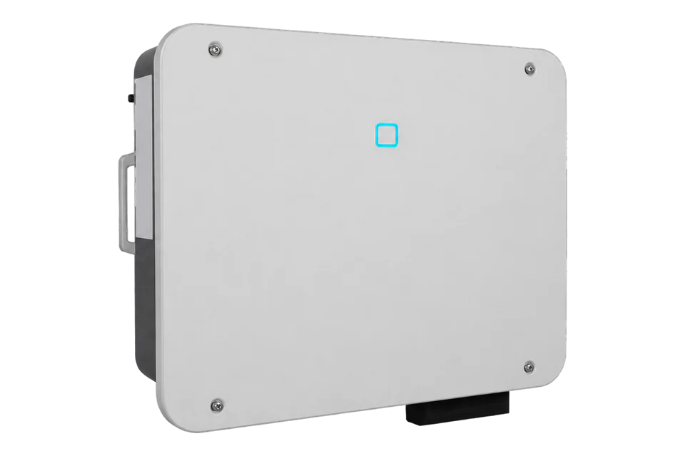
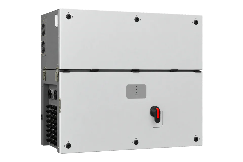
Sungrow SG25-50CX-P2
Commercial PV inverter
Sungrow SG25CX-P2, SG30CX-P2, SG33CX-P2, SG36CX-P2, SG40CX-P2 and SG50CX-P2 inverters connect to EpiSensor Edge over Modbus RTU on the COM2 RS485 terminals, or over Modbus TCP through a WiNet-S module. Sungrow's public protocol V1.1.80 gives the device type code for each model and FC04 running data. Read the device type first, then active power, and compare with the iSolarCloud or local reading.
Compatibility
Compatible with EpiSensor Edge over Modbus RTU or Modbus TCP
The SG25-50CX-P2 user manual Ver114 documents RS485 terminals A1 and B1 on COM2 for monitoring devices. Sungrow's Communication Protocol of Residential & Commercial PV Grid-Connected Inverters V1.1.80 lists every model in this family with its device type code and defines read-only FC04 running registers. Edge reads them as a Modbus RTU client through a ZMB-31 Modbus Interface or the Gateway serial port, or as a Modbus TCP client through the WiNet-S Ethernet port.
SG25CX-P2, SG30CX-P2, SG33CX-P2, SG36CX-P2, SG40CX-P2 and SG50CX-P2 (global versions), from user manual SG25_30_33_36_40_50CX-P2-UEN-Ver114-202604 and protocol V1.1.80 of 27 March 2026. The CN, P2H, LV and JP variants have other device type codes. Site check: read the device type code and nominal power, then compare active power with the inverter's own reading.
Connect it with


When COM2 RS485 is free for one polling master and no WiNet-S or logger uses the inverter's monitoring link
- Modbus
- Wireless
- Edge
- Platforms
When a WiNet-S or WiNet-S2 module is fitted on COM1 and connected to the site network by Ethernet
- Modbus
- Edge
- Platforms
Models
| Models | Interface | Route into Edge |
|---|---|---|
| SG25CX-P2 / SG30CX-P2 / SG33CX-P2 | 25, 30 or 33 kW; three MPPTs; device type codes 0x2C33, 0x2C34 and 0x2C35 | Read MPPT 1 to 3 at 5011 to 5016 and total active power at 5031 to 5032. |
| SG36CX-P2 / SG40CX-P2 / SG50CX-P2 | 36, 40 or 50 kW; four MPPTs; device type codes 0x2C36, 0x2C37 and 0x2C32 | Add MPPT 4 at 5115 to 5116; the rest of the running map is the same. |
| SG33CX / SG40CX / SG50CX (first generation) | Device type codes 0x2C00, 0x2C01 and 0x2C02 in the same protocol | The register map applies; take the wiring from that model's own manual, not the P2 terminal labels. |
Specifications
The SG-CX-P2 family covers 25 to 50 kW three-phase string inverters with two PV strings per MPPT, three MPPTs on the 25, 30 and 33 kW models and four on the 36, 40 and 50 kW models. COM2 carries the RS485 monitoring port, the meter port and the DI, DRM and DO contacts; COM1 takes a Sungrow communication module.2
- Rated AC output power
- 25, 30, 33, 36, 40 and 50 kW2
- Maximum AC output power
- 27.5, 33, 36.3, 40, 44 and 55 kVA (SG30CX-P2: 30 kVA in Germany, Belgium, Austria, Ukraine and Denmark)2
- Max. PV input voltage
- 1100 V2
- Communication
- RS485; WLAN and Ethernet through an optional module2
- RS485 defaults
- Slave address 1 (1 to 247), 9600 bit/s, 8 data bits, 1 stop bit, RTU; parity none or settable1
- Modbus TCP
- Through WiNet-S, WiNet-S2 or Logger1000 Ethernet, port 502, DHCP by default1
- Degree of protection
- IP66, corrosion class C52
- Operating ambient temperature
- -30 to 60 °C; altitude up to 4000 m2
Interface
Documented measurements and integration boundaries for SG25-50CX-P2.
- FC04 input registers. Sungrow numbers registers from 5000 and the address sent is one less: register 5000 is wire address 4999 (0x1387).
- Identity: 4990 to 4999 serial number (UTF-8), 5000 device type code (U16), 5001 nominal active power (U16, 0.1 kW), 5002 output type (0 two phase, 1 3P4L, 2 3P3L).
- Energy: 5003 daily yield (U16, 0.1 kWh), 5004 to 5005 total yield (U32, kWh), 5144 to 5145 total yield (U32, 0.1 kWh).
- AC: 5019 to 5021 phase or line voltage (U16, 0.1 V, chosen by output type), 5022 to 5024 phase currents (U16, 0.1 A), 5031 to 5032 total active power (S32, W), 5033 to 5034 reactive power (S32, var), 5035 power factor (S16, 0.001), 5036 grid frequency (U16, 0.1 Hz), 5148 grid frequency (U16, 0.01 Hz).
- DC: 5011 to 5016 MPPT 1 to 3 voltage and current (0.1 V, 0.1 A), 5115 to 5116 MPPT 4, 5017 to 5018 total DC power (U32, W), 7013 onward string currents (U16, 0.01 A) where the hardware supports them.
- State: 5038 work state 1 (0x0 run, 0x8000 stop, 0x1400 standby, 0x5500 fault, 0x9100 alarm run), 5008 internal temperature (S16, 0.1 °C), 5071 array insulation resistance (U16, 1 kΩ).
- 32-bit values send the low-order register first: U32 0x01020304 arrives as 03 04 01 02. Unavailable reads return 0xFFFF (U16), 0xFFFFFFFF (U32), 0x7FFF (S16) or 0x7FFFFFFF (S32).
Assessment
SG25CX-P2, SG30CX-P2, SG33CX-P2, SG36CX-P2, SG40CX-P2 and SG50CX-P2, from user manual Ver114 (April 2026) and protocol V1.1.80 (27 March 2026). Record the device type code and compare the first reads with the inverter's own reading.
- InteroperabilitySupported with conditions
- The public protocol gives serial settings, address convention, word order, device type codes and FC04 running registers; RS485 and module links are mutually exclusive for a logger.12
- AccuracySupported with conditions
- Active and reactive power, phase quantities, MPPT values and energy counters carry documented types and scales. Inverter values do not replace a meter at the point of connection.1
- SecurityNot yet assessed
- The protocol defines no authentication or encryption for RS485 or Modbus TCP reads.1
- ReliabilityNot yet assessed
- The protocol defines unavailable values but no polling interval, recovery or backfill behaviour for third-party clients.1
- RuggednessWell supported
- The manual gives IP66, corrosion class C5, -30 to 60 °C and operation up to 4000 m.2
Setup
Identify an SG50CX-P2, then decode active power
Sungrow registers start at 5000 for running data; the address sent is the register minus one, with FC04. Slave address 1 is the default. These are synthetic decoder checks with correct CRCs, not captured inverter responses.
- Identity request
- 01 04 13 87 00 02 C5 66 reads registers 5000 and 5001 from wire address 4999. The protocol's own example sends 01 04 1387 00 02 + CRC for the same registers.
- Synthetic identity reply
- 01 04 04 2C 32 01 F4 52 CC gives device type 0x2C32, the SG50CX-P2, and nominal active power 0x01F4 = 500 × 0.1 kW = 50.0 kW.
- Power request
- 01 04 13 A6 00 02 95 6C reads total active power at registers 5031 and 5032 from wire address 5030.
- Synthetic power reply
- 01 04 04 C3 50 00 00 C7 D1: low word 0xC350 arrives first, high word 0x0000 second, so the S32 value is 0x0000C350 = 50000 W.
- Unavailable value
- Data FF FF 7F FF combines high word 0x7FFF and low word 0xFFFF into 0x7FFFFFFF, the S32 unavailable value. Do not plot it as generation.
Acceptance: Accept the read when the device type matches the nameplate model and active power agrees with the inverter's own reading. If the code is not in the SG25-50CX-P2 list, use the protocol's appendix 1 for the installed model before mapping MPPT inputs.
-
Choose one monitoring link
Use either COM2 RS485 (A1 and B1) or a WiNet-S module on COM1. The user manual says that once a communication module is in use, a data logger must not be connected on RS485 at the same time. Keep A2 and B2 for the Smart Energy Meter.
-
Match the serial settings
This guide uses protocol V1.1.80 and user manual Ver114. The protocol gives slave address 1 by default (settable from 1 to 247), 9600 bit/s, 8 data bits, 1 stop bit and RTU mode; parity is none or settable. Keep one Modbus master on the line.
-
Read the device type code first
Send FC04 to wire address 4999 (register 5000), quantity 2. The first word is the device type code (0x2C32 for SG50CX-P2, 0x2C35 for SG33CX-P2) and the second is nominal active power in 0.1 kW. Record both with the nameplate before reading measurements.
-
Decode 32-bit values low word first
Total active power is S32 at registers 5031 to 5032: send FC04 to 5030, quantity 2. Sungrow sends the low-order word first, so combine as high × 65536 + low and subtract 4294967296 if bit 31 is set. A reply of 0x7FFFFFFF is unavailable, not real power.
-
Compare and keep control out of scope
Compare active power and grid frequency with the iSolarCloud or local app reading while the inverter is running (work state 0x0). The RW registers in section 2.2 (start and stop, power limits) use FC03, FC06 and FC10 and are outside this guide; control needs the site owner's and Sungrow's agreement.
Common questions
- Which function code does the SG50CX-P2 use for running data?
- FC04, read input registers. Table 3 of the protocol marks the running information as read-only with Modbus command 0x04. The parameter registers in table 4 use FC03, FC06 and FC10.1
- Why is register 5031 sent as address 5030?
- The protocol says to visit every register by subtracting 1 from its address: register 5000 to 5001 is read at address 4999 to 5000. The same rule moves 5031 to 5030.1
- Can I use COM2 RS485 and a WiNet-S module at the same time?
- The user manual says that once a communication module is in use, the inverter must not be connected to a data logger over RS485 at the same time. Choose one monitoring link for Edge.2
- How do I tell an SG36CX-P2 from an SG40CX-P2 over Modbus?
- Read register 5000. The SG36CX-P2 returns 0x2C36 and the SG40CX-P2 returns 0x2C37. Both have four MPPTs, so the device type, not the MPPT count, identifies the model.1
Related devices
Sources
- Communication Protocol of Residential & Commercial PV Grid-Connected Inverters V1.1.80, 27 March 2026 (opens in a new tab) (PDF)
- SG25CX-P2/SG30CX-P2/SG33CX-P2/SG36CX-P2/SG40CX-P2/SG50CX-P2 user manual, Ver114, April 2026 (opens in a new tab) (PDF)
Further reading
- ApplicationSolar inverter monitoring across a PV fleet
- GuideSungrow SG110CX
- GuideSungrow SG125CX-P2
- ToolModbus data decoder
- ToolPV string sizing
- ToolModbus register address converter
- ToolRS-485 termination and bias
- ManufacturerSungrow devices
- ProtocolModbus devices and register maps
- CategoryInverters and charge controllers
Product names and trademarks belong to their owners. Publication does not imply endorsement or a commercial relationship.