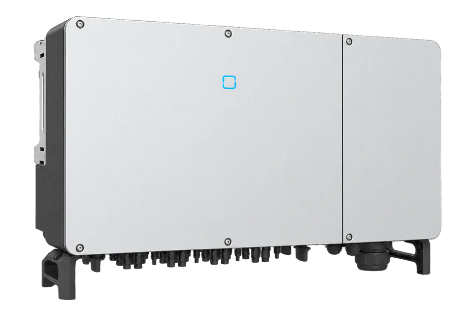
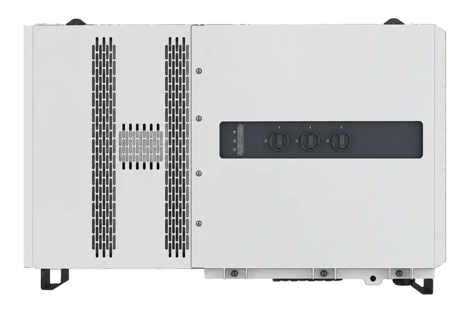
Sungrow SG110CX
Commercial PV inverter
The original SG110CX has nine MPPTs and two strings per MPPT. It is distinct from the later CX-P2 and CX-P3 platforms even though their names share the same power class. The current communication protocol still identifies the original model explicitly as type 0x2C06. That type check provides a useful commissioning boundary before adopting a measurement map.
- Modbus RTU
Commercial PV inverter
Compatibility
Compatible through Modbus RTU
Sungrow publishes a current PV inverter map with the exact original SG110CX type code, read function and data formats. The installation manual defines the serial monitoring interface.
Original SG110CX, using its official user manual revision 18 (June 2021) and Residential & Commercial PV protocol V1.1.80 (27 March 2026). Appendix 1 explicitly identifies SG110CX as 0x2C06. SG110CX-20, NI, P2 and P3 are separate variants. The retained protocol establishes no minimum firmware for this exact read; verify the installed software and device type before commissioning.
Connect it with
-
Modbus Interface ZMB-3XFrom €399 ex VAT Configure Modbus Interface
-
Gateway ZGW-20From €899 ex VAT Configure Gateway


An approved exclusive-master serial path is available
- Modbus
- Edge
- Platforms
Models
| Models | Interface | Route into Edge |
|---|---|---|
| Original SG110CX | Nine MPPTs, type 0x2C06 | Use RS485_1 and the original-model protocol applicability. |
| SG110CX-20 / NI / P2 / P3 | Different variant or generation | Use their exact manual and type code; no automatic inheritance. |
Specifications
The installation manual assigns RS485_1 to the logger and monitoring connection. Its terminal block and RJ45 connectors are two wiring forms of that serial interface, not independent clients or an Ethernet socket. A site with an existing logger already has an RTU master: agree an approved upstream monitoring path or a planned bus-ownership change instead of attaching a second master. Optional Ethernet equipment requires its own documented setup and is outside this guide.1
- AC output envelope
- 110 kVA at 45 °C or 100 kVA at 50 °C; nominal three-phase 230/400 V1
- PV configuration
- Nine MPPTs with two strings per MPPT; not the P2 or P3 generation2
- Monitoring bus
- RS485_1: A1 signal positive, B1 signal negative, PE shield point1
- RJ45 distinction
- RS485_1 RJ45 pin 3 is B and pin 6 is A; this connector is not Ethernet1
- Serial defaults
- 9600 bit/s, 8 data bits, no parity, 1 stop bit; address 1 by default, settable 1–247. Verify installed values.2
- Power read
- FC04, documented registers 5031–5032; wire address 5030, signed 32-bit watts2
- Word order
- For 32-bit values: low 16-bit word first, big-endian bytes within each word2
- Environment
- IP66; -30 to +60 °C, derating above +50 °C; altitude up to 4000 m with derating above 3000 m1
Interface
Documented measurements and integration boundaries for SG110CX.
- Individual inverter active and reactive power from the applicable running-information map.
- Phase measurements, frequency and energy counters with documented types and scales.
- Device type, serial identity and software fields for the commissioning record.
Assessment
Original SG110CX, using its official user manual revision 18 (June 2021) and Residential & Commercial PV protocol V1.1.80 (27 March 2026). Appendix 1 explicitly identifies SG110CX as 0x2C06. SG110CX-20, NI, P2 and P3 are separate variants. The retained protocol establishes no minimum firmware for this exact read; verify the installed software and device type before commissioning.
- InteroperabilitySupported with conditions
- The exact model documentation establishes the local interface and identity checks. The installed configuration and existing site controller must be preserved.12
- AccuracySupported with conditions
- The measurement representation and units are documented, but inverter telemetry does not establish revenue-meter accuracy.2
- SecurityNot yet assessed
- The proposed local monitoring path does not establish authenticated or encrypted measurements. Restrict access to the approved site network.1
- ReliabilityNot yet assessed
- No measured availability or guaranteed historical backfill is established for this direct monitoring connection.2
- RuggednessSupported with conditions
- The exact manual specifies the enclosure rating and temperature limits, with option or derating conditions that must be retained.1
- ScalabilitySupported with conditions
- Serial daisy chains require unique addresses, correct termination and a single master; the existing logger limits the available monitoring topology.1
Setup
Identify the original CX and decode active power
These are synthetic request and data examples, not captured inverter responses. Use the actual configured RTU address and a complete CRC-checked frame.
- Identity PDU
- 04 13 87 00 01 reads FC04 at wire address 4999, quantity 1. Data 2C 06 identifies original SG110CX.
- Power PDU
- 04 13 A6 00 02 reads wire address 5030, quantity 2, corresponding to documented 5031–5032.
- Synthetic data
- AD B0 00 01 means low word 0xADB0, high word 0x0001. Combined 0x0001ADB0 is signed 110000 W.
- Unavailable
- FF FF 7F FF combines to 0x7FFFFFFF, the signed unavailable sentinel. Do not report it as generated power.
- Frame boundary
- The PDU omits the configured slave address and CRC16. Validate those plus the response function and byte count before accepting data.
Acceptance: Accept only after exact device type, framing, decoded units and live reference agree. A successful measurement does not authorise dispatch, grid-setting or protection writes.
-
Check the original model and software
Original SG110CX, using its official user manual revision 18 (June 2021) and Residential & Commercial PV protocol V1.1.80 (27 March 2026). Appendix 1 explicitly identifies SG110CX as 0x2C06. SG110CX-20, NI, P2 and P3 are separate variants. The retained protocol establishes no minimum firmware for this exact read; verify the installed software and device type before commissioning.
-
Agree serial-bus ownership
Identify the existing logger and plant controller before wiring. Do not add a second RTU master to its bus or disconnect operational control to obtain a reading. Use an approved logger export or an engineered exclusive-master arrangement; this guide does not establish that upstream export automatically.
-
Use the documented monitoring interface
Use RS485_1 A1/B1 and the shield point as specified by the manufacturer. Its RJ45 option carries RS-485 on pins 3 and 6, not Ethernet. Keep other serial, tracker, alarm and local-stop connections unchanged. Follow the site’s qualified installation and termination design.
-
Verify serial settings
Read the configured address and framing. The protocol defaults are 9600 bit/s, 8N1 and address 1; do not assume an installed unit still uses them. Use one unique address per inverter and validate RTU CRC16 on every complete response.
-
Read identity with the correct function
Read FC04 at documented register 5000 using wire address 4999, quantity 1. Require type 0x2C06 for this guide. The same numeric addresses in read/write tables are not substitutes: do not use FC03 for this running-information read.
-
Decode a bounded active-power read
Read FC04 at wire address 5030, quantity 2. Combine the first register as the low word and the second as the high word, then interpret the result as signed 32-bit watts. The signed unavailable sentinel is 0x7FFFFFFF, not the SunSpec 0x80000000 convention. Compare with the inverter and a suitable live reference before expanding the point list.
Common questions
- Can I connect beside the existing logger?
- Not as a second RTU master on the same bus. Coordinate an authorised upstream path or a planned exclusive-master design with the system owner. Two physical connector forms do not create two independent serial buses.1
- Does 5031 go directly into the Modbus request?
- No. Sungrow’s table uses one-based register numbers and explicitly requires subtracting one. The active-power pair 5031–5032 therefore begins at wire address 5030.2
- Can I reuse the hybrid SH10RT map?
- No. This is the PV grid-connected inverter protocol and an exact SG110CX type check. Hybrid products and newer CX generations have separate applicability and operating boundaries.2
Related devices
Sources
- SG110CX user manual, revision 18, June 2021 (opens in a new tab) (PDF)
- Residential & Commercial PV Grid-Connected Inverter protocol V1.1.80, March 2026 (opens in a new tab) (PDF)
Further reading
Product names and trademarks belong to their owners. Publication does not imply endorsement or a commercial relationship.