Acrel ADL400
Three-phase energy meter
The ADL400 is Acrel's three-phase DIN-rail multifunction energy meter. It measures voltage, current, power, power factor, frequency and harmonics to the 31st, counts forward and reverse active and reactive energy, and has an RS-485 port on terminals 21 and 22 running Modbus RTU. It comes as a direct-connected 3 × 10(80) A meter and as a 3 × 1(6) A meter for current transformers, and the F option adds tariffs, maximum demand and monthly history. Acrel prints the register addresses in hexadecimal and gives most instantaneous values as one-register integers with a fixed resolution, so L1 voltage at 0x0061 arrives in tenths of a volt.

Compatibility
Compatible with EpiSensor Edge over Modbus RTU
The ADL400 is compatible with EpiSensor Edge over its RS-485 Modbus RTU port, read through a ZMB-31 Modbus Interface or a Gateway serial port. Acrel publishes the FC03 register map with hexadecimal addresses, register lengths and resolutions, and its own example request confirms the address convention.
ADL400 direct-connected 3 × 10(80) A and CT-operated 3 × 1(6) A meters, with or without the F multi-tariff option, using the Table 8 register list in the ADL400 installation and operation instruction V1.3. Site check: compare the first voltage read with the meter display before adding points. Read-only monitoring: no writes to the address, baud, PT, CT, password, clock or tariff registers.
Connect it with
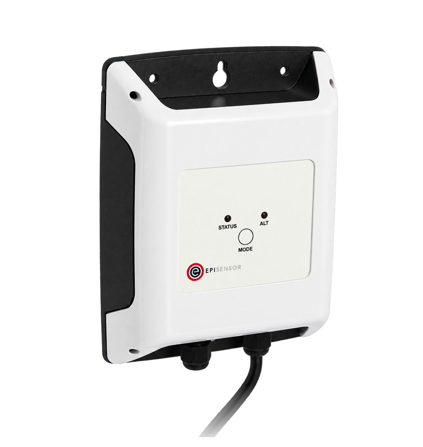
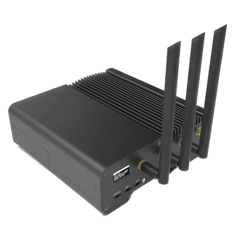
For a meter in a distribution board where a wireless link avoids running a data cable back to the Gateway
- Modbus
- Wireless
- Edge
- Platforms
When the Gateway sits near the meter, or several meters share one wired RS-485 bus
- Modbus
- Edge
- Platforms
Models
| Models | Interface | Route into Edge |
|---|---|---|
| ADL400, 3 × 10(80) A | Load current through the meter's own terminals; RS-485 Modbus RTU on 21 and 22; active energy pulse output on 17 and 18 | Read the Table 8 registers with FC03 on the serial path. |
| ADL400, 3 × 1(6) A | Current inputs for external current transformers with the CT ratio set on the meter (Ct, 1 to 9999); the same RS-485 port and map | Same read path. Confirm the CT ratio on the meter and compare current and power with the display before trusting the values. |
| ADL400-F | Adds four tariffs, maximum demand with the time it occurred, a date and time clock, and 48 months or 90 days of frozen history | Tariff, demand, clock and history registers hold data only on F meters; the manual says the date, time, maximum demand and tariff energy do not exist without the multi-tariff function. |
Specifications
- Versions
- ADL400 direct connected, 3 × 10(80) A. ADL400 CT operated, 3 × 1(6) A. ADL400-F adds multi-rate energy statistics, demand and history.1
- Voltage
- Reference voltage 3 × 100 V, 3 × 380 V, 3 × 57.7/100 V or 3 × 220/380 V; three-phase three-wire or four-wire; 45 to 65 Hz.1
- Accuracy
- Active energy class 0.5 and reactive energy class 2; voltage and current error ±0.2%, power ±0.5%, frequency ±0.2%. The manual cites IEC 62053-21.1
- MID test report
- Acrel publishes an SGS approval report under MID Annex II module B (EN 50470-1 and EN 50470-3) for type ADL400, class A, B or C, tested as a 3 × 230/400 V, 1(6) A, 10000 imp/kWh meter. Check the label of the installed meter for its own marking.2
- RS-485
- Modbus RTU on terminals 21 (A1) and 22 (B1). Address 1 to 247; 1200, 2400, 4800, 9600 or 19200 bit/s; parity none, odd or even in the settings menu. Shielded twisted pair, no longer than 1200 m.1
- Pulse output
- One active energy photocoupler output on terminals 17 (Ep+) and 18 (Ep-), 80 ± 20 ms wide; 400 imp/kWh or 10000 imp/kWh depending on the version.1
- Housing
- DIN-rail case of 90 × 72 × 65 mm in the dimension drawings. Terminal torque 3 to 4 N·m on the direct version and 1.5 to 2 N·m on the CT version.1
Interface
Documented measurements and integration boundaries for ADL400.
- Addresses are hexadecimal PDU addresses: 0061H is sent as 00 61 (decimal 97). Read with FC03; the map's writes use FC10 (16). The manual's own event-log request 01 03 30 01 00 06 9B 08 sends 3001H exactly as printed.
- The Length column counts bytes, not registers: 2 is one register and 4 is two. The manual confirms it for the history block, 120 bytes in 60 registers.
- Phase voltage A, B and C at 0x0061, 0x0062 and 0x0063: one register each, resolution 0.1 V. Line voltages A-B, C-B and A-C at 0x0078, 0x0079 and 0x007A: one register each; the table prints no resolution for them, so compare one with the display.
- Current A, B and C at 0x0064, 0x0065 and 0x0066: one register each, resolution 0.01 A.
- Active power A, B, C and total at 0x0067 to 0x006A: one register, two's complement, resolution 0.001 kW (the table prints kWh). Reactive power at 0x006B to 0x006E (0.001 kvar) and apparent power at 0x006F to 0x0072 (0.001 kVA) follow the same pattern.
- A one-register value at 0.001 kW can only hold ±32.767 kW. For larger loads read the two-register powers: active A, B, C and total at 0x0164, 0x0166, 0x0168 and 0x016A (0.0001 kW, two's complement), reactive at 0x016C to 0x0172 and apparent at 0x0174 to 0x017A.
- Power factor A, B, C and total at 0x0073 to 0x0076: two's complement, resolution 0.001. Frequency at 0x0077: resolution 0.01 Hz. Voltage and current imbalance at 0x0093 and 0x0094: resolution 0.001.
- Total active energy at 0x0000, forward active energy at 0x000A and reverse active energy at 0x0014: two registers each, each followed by its spike, peak, flat and valley tariff counters. The V1.3 table leaves the unit cell blank for the active rows, so compare one with the display before setting the scale.
- Total reactive energy at 0x001E, forward at 0x0028 and reverse at 0x0032: two registers, integer in kvarh with two decimal places. Forward active energy on phases A, B and C at 0x0087, 0x0089 and 0x008B: two registers each.
- A floating-point copy of the instantaneous values starts at 0x5300: phase voltages 0x5300 to 0x5304, line voltages 0x5306 to 0x530A, currents 0x530C to 0x5310, active power 0x5312 to 0x5318, reactive power 0x531A to 0x5320, apparent power 0x5322 to 0x5328, power factor 0x532A to 0x5330, frequency 0x5332 and neutral current 0x5334, two registers each. The manual gives no word order or unit for this block; check it against the integer registers.
- Voltage THD A to C at 0x05DD to 0x05DF and current THD A to C at 0x05E0 to 0x05E2: one register each with three decimal places; individual harmonics 2 to 31 follow from 0x05E3.
- Settings are readable and writable: address and baud code at 0x003F, parity and stop-bit codes at 0x0095, PT at 0x008D, CT at 0x008E, password at 0x00A6 and the clock at 0x003C to 0x003E. Keep them out of a monitoring poll.
Assessment
ADL400 direct-connected 3 × 10(80) A and CT-operated 3 × 1(6) A meters, with or without the F multi-tariff option, using the Table 8 register list in the ADL400 installation and operation instruction V1.3. Site check: compare the first voltage read with the meter display before adding points. Read-only monitoring: no writes to the address, baud, PT, CT, password, clock or tariff registers.
- InteroperabilitySupported with conditions
- Acrel documents Modbus RTU on RS-485 with FC03 reads, hexadecimal addresses, lengths and resolutions, and its own example frame confirms the address convention. The manual does not state the word order of two-register values or the unit of the active energy rows, so those need one comparison with the display.1
- AccuracySupported with conditions
- Class 0.5 active and class 2 reactive energy with per-phase voltage, current, power and power factor, forward and reverse energy and harmonics to the 31st. The one-register powers saturate at 32.767 kW, so larger loads need the two-register powers, and CT-operated meters depend on the CT ratio set on the meter.1
- SecurityNot yet assessed
- A four-digit code protects the keypad settings menu, but the password, address, baud, PT, CT and clock registers are all listed as writable over Modbus.1
- ReliabilitySupported with conditions
- The meter keeps a 100-entry event record readable from 0x3001, covering power on and off, counter clears, over-voltage, loss of voltage, current reversal, over-current and time calibration, and the SGS report records the type tests to EN 50470 as complied. The manual gives no exception codes or response times; treat failed reads as missing data.12
- RuggednessSupported with conditions
- Rated -25 to +55 °C and up to 95% relative humidity, non-condensing; the SGS report covers the type tested over the same temperature range. The manual gives no IP rating for the front or terminals.12
- ScalabilitySupported with conditions
- Addresses 1 to 247 and an RS-485 bus up to 1200 m are documented. The highest baud rate is 19200 bit/s and the manual does not state how many meters one segment carries, so the poll list and bus loading set the practical limit.1
- LifecycleNot yet assessed
- The manual's revision record runs from V1.0 (2019) to V1.3 (2021) and the display shows the software version, but no support period is stated.1
Setup
Read phase A voltage from hexadecimal address 0x0061
ADL400 installation and operation instruction V1.3, Table 8, lists Voltage of A phase at address 0061H, length 2 (one register), read-only, resolution 0.1 V. Use that map as the starting point and compare the result with the display.
- Request
- 01 03 00 61 00 01 D5 D4: Modbus address 1, FC03, address 0x0061, one register, RTU CRC.
- Address convention
- The table address is hexadecimal and goes on the wire as printed, as the manual's own request 01 03 30 01 00 06 9B 08 for 3001H shows. 0x0061 is decimal 97 as a zero-based PDU address; a client that numbers holding registers from one shows it as 98 (40098). Do not send decimal 61.
- Synthetic response
- 01 03 02 08 FC BF C5: two data bytes, 08 FC.
- Decode
- One 16-bit register, high byte first: 0x08FC = 2300. The resolution is 0.1 V, so 2300 × 0.1 = 230.0 V.
- Acceptance
- Keep the point when it agrees with phase A voltage on the meter display at the same time. If it does not, check the address, the PT setting and whether the client has added one to the address before adding more points.
Acceptance: The response bytes are a synthetic decoder check, not a captured meter reply. A real reply must agree with the display before current, power and energy points are enabled.
-
Identify the meter
Read ADL400 and the current rating from the front label: 3 × 10(80) A for the direct version, 3 × 1(6) A for the CT version. Note whether it is an F meter, and for the CT version record the CT ratio set on the meter.
-
Read the serial settings on the display
One display page shows the parity, baud rate, meter address and software version. Enter the same address, baud rate and parity in the Edge serial client or the ZMB-31 and leave the meter's own settings unchanged.
-
Wire the RS-485 pair
Connect A to terminal 21 and B to terminal 22 with shielded twisted pair, use one colour for every A conductor, and give each meter on the bus its own address. Keep the bus under 1200 m.
-
Make one voltage read
Send FC03 to address 0x0061 for one register and divide the result by 10, as in the worked read below. Compare it with phase A voltage on the display.
-
Add the points you need
Add current, power, power factor and the energy counters from Table 8. Use the two-register powers above 32 kW, confirm the active energy scale against the display, and keep FC10 writes out of the polling configuration.
Common questions
- Is 0061H register 61?
- No. Acrel prints the ADL400 addresses in hexadecimal, which is why the map has entries such as 000AH and 006FH. Send 0x0061, decimal 97, as the PDU address. A tool that asks for one-based holding register numbers needs 98, or 40098.1
- Why does the map give voltage a length of 2?
- The Length column counts bytes. Voltage at 0x0061 is one 16-bit register, and the energy counters with a length of 4 are two registers. The manual's history block, 120 bytes in 60 registers, follows the same rule.1
- Why does total active power stop at 32.767 kW?
- The one-register power at 0x006A is a signed 16-bit value with 0.001 kW resolution, so it cannot hold more than 32.767 kW. Read the two-register total at 0x016A instead, which has 0.0001 kW resolution and is also signed.1
- Which energy counter measures consumption?
- Forward active energy at 0x000A counts import and reverse active energy at 0x0014 counts export; total active energy at 0x0000 is the combined counter. If forward and reverse appear swapped, check the DIR setting and the CT orientation on the meter rather than relabelling the points in Edge.1
- Does the ADL400 have Modbus TCP?
- Not in this manual. It documents one RS-485 port with Modbus RTU. Edge reads it through a ZMB-31 Modbus Interface or a Gateway serial port.1
- Can the ADL400 be used for billing under MID?
- Acrel publishes an SGS MID Annex II module B approval report for type ADL400, tested as a 3 × 230/400 V, 1(6) A CT-operated meter. Whether a particular meter is MID marked is shown on its own label; check it before using the readings for billing.2
Related devices

Sources
- ADL400 installation and operation instruction V1.3, with the Modbus-RTU communication address list (Table 8) and floating-point block (opens in a new tab) (PDF)
- SGS approval report SHES210300438001 for the pattern and construction of electricity meters, MID Annex II module B, type ADL400 (issued 25 August 2021) (opens in a new tab) (PDF)
Further reading
Product names and trademarks belong to their owners. Publication does not imply endorsement or a commercial relationship.