Battery energy storage monitoring and local control
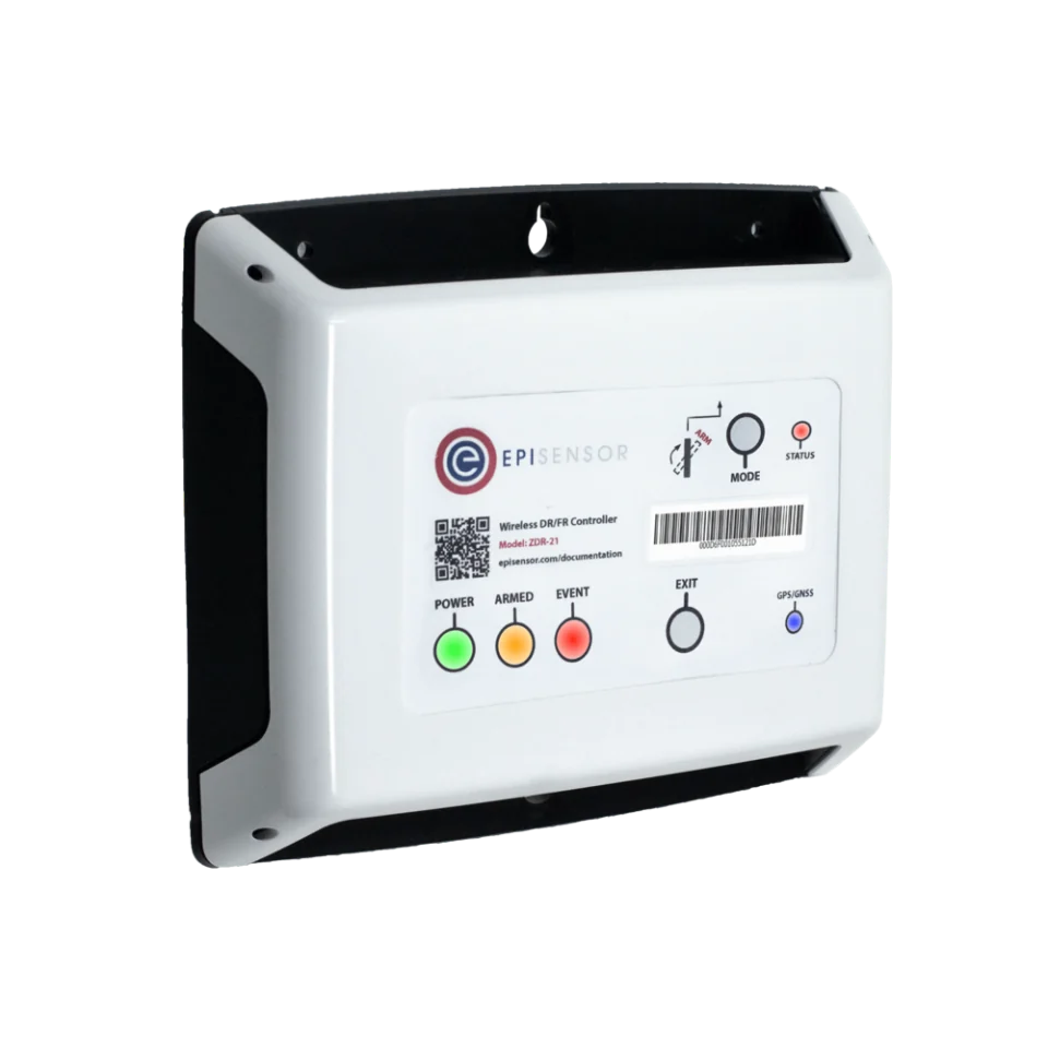
Measure the battery, its connection and operating limits as separate records. Where the exact approved contract exists, a Demand Response Controller can send and verify a local request.


- Measure
- Connection and battery AC power, state of charge, charge and discharge limits, alarms, auxiliaries and command response
- Good practice
- A BESS monitoring system records requested, accepted, permitted and measured power as different values
- Sensors
- ZEM-65, for suitable low-voltage AC circuits; utility and medium-voltage projects retain their approved plant meters and transducers Wireless 3-Phase Electricity Monitor datasheet
- On site
- ZGW-20 Gateway, runs Edge locally for records, alarms and bounded automation without depending on a cloud connection Gateway datasheet
Choose the electrical boundary before choosing the meter
A commercial battery connected at low voltage may have an accessible feeder that can be metered independently. A utility or medium-voltage project already has engineered plant metering, protection, a power plant controller and operator interfaces. Integrate those approved systems; do not replace them with a panel meter or infer settlement values from an operating meter.
| Commercial and industrial LV | Utility or MV project | |
|---|---|---|
| Operating measurement | An independent meter may be added on a suitable LV battery feeder | Read the approved plant meter or transducer through its engineered interface |
| Control authority | Site EMS or an approved local controller, with one active writer | Power plant controller or EMS within the grid-code design |
| Systems that remain | BMS, PCS protection, fire system and site protection | Plant protection, PPC, safety systems, operator telemetry and revenue or settlement metering |
Hardware for battery performance records
Use the Gateway for the local record, add only the interfaces that match documented plant boundaries, and enable control only through an exact commissioned contract.
Runs Edge locally, keeps the time-series and event record, and exports approved data onward
1 per site up to 250 wireless devices
Only where the commissioned PCS or EMS exposes the exact approved Modbus control contract
Measures at the connection and sends a changing set point to a battery or UPS over Modbus
1 per approved control path RS-485 Modbus RTU master for up to 4 devices
- Choose the CT type for the approved connection measurement: mini-CTs on existing 1 A or 5 A CTs, or Rogowski coils at 1 kA and 3 kA
Frequency sampled at 100 ms or better at 0.01 Hz, 20 ms event recording and GPS time synchronisation
For suitable low-voltage circuits only
Independent battery-feeder or auxiliary-load power where the circuit is within the product's rated installation boundary
1 per required LV boundary three-phase, 3 or 4 wire
- Choose the CT rating for a suitable low-voltage AC circuit: 120 A split-core, or 300 A, 1 kA and 3 kA Rogowski coils
Class 0.5S to IEC 62053-22 with its CTs, 110 to 480 V line to line, CAT III at 480 V
Where the exact equipment and register map provide an approved RS-485 Modbus RTU path

Reads documented BMS, PCS, EMS or approved plant-meter registers over an available RS-485 Modbus RTU path
1 per available bus up to 30 registers
Modbus RTU over RS-485, function codes 1 to 6, 15 and 16; it is not a transparent gateway
Measurements that explain storage performance
A useful record separates the electrical result from the equipment's state and from the request sent to it. Keep each value's unit, sign, timestamp, quality and source.
From field measurement to Edge
Each field signal reaches its named EpiSensor interface, reports through the site Gateway and is handled locally in Edge.
- Control
- Zigbee
- Wired
- Edge
- Platforms
| Position | What it tells you | Reference | Sensor |
|---|---|---|---|
| Point-of-connection power | The import or export the grid and site actually saw | Use the project's approved operating meter and sign convention; keep settlement metering separate IEC 62933-3-1 | ZDR-22 (on this page), connection measurement |
| Battery and auxiliary AC power | Battery contribution, conversion losses and loads such as cooling | Record which auxiliaries sit inside each measurement boundary IEC 62933-3-1 | ZEM-65 (on this page), suitable LV circuits |
| BMS, PCS and EMS state | State of charge, permitted power, alarms, contactors, operating mode and active set point | Bind every point to the supplier's exact register map and firmware version SMA | ZMB-31 (on this page), documented registers |
| Control request and measured response | What was requested, accepted, permitted and then delivered | A successful write is not evidence that the requested power was delivered EirGrid | ZDR-22 (on this page), approved control path |
One system writes the active-power set point. Name the control authority for every operating mode. A site EMS, PPC, aggregator request and local frequency controller must not compete for the same PCS register.
The BMS keeps authority over battery safety. External monitoring and control never override cell limits, contactors, trips or the charge and discharge limits produced by the BMS.
Revenue data has a separate owner. Operational meters support diagnostics and verification. They do not become the market, billing or settlement record unless the responsible authority has approved them for that purpose.
Local BESS records and bounded control in Edge
Edge combines fresh plant data and independent measurements on site. Any write path is explicit, expires safely and is checked against measured power.
- Keep request and result apart
- Record the command ID, source, requested power, acceptance, permitted power, measured power and configuration version as distinct fields.
- Withdraw stale availability
- If the meter, BMS limits or operating state become stale, calculated availability falls to unavailable rather than repeating the last good value.
- Expire every external command
- Use the equipment's approved watchdog or reversion mechanism and reject delayed commands. The project engineer chooses the fallback state for the real site.
- Verify response from a meter
- Read-back confirms only what the controller reports. Compare it with a fresh operating measurement at the declared boundary and retain both records.
- Keep the control network bounded
- Only the named controller reaches the write interface. Segment OT traffic and keep monitoring clients read-only where they do not own control.
Commissioning checks
Commission monitoring first. Enable a control path only with the battery supplier and the engineer responsible for the site's controls, protection and grid-code design.
-
Every sign and unit agrees
During a small approved charge and discharge, compare the connection meter, battery meter, PCS and Edge values with timestamps visible.
Pass when each value moves in the documented direction, uses the expected scale and can be reconciled to its measurement boundary.
-
Operating limits remain current
Compare state of charge, alarms, contactor state and permitted charge and discharge power with the supplier interface across changing conditions.
Pass when the values, units and quality match, and a stale source makes availability unavailable.
-
Only the named writer can command
Inspect network access and each operating mode, then attempt a write from an unauthorised monitoring client under the approved test plan.
Pass when the active authority is visible, other clients remain read-only and simultaneous writers cannot reach the PCS control point.
-
The response is measured independently
Issue a bounded approved request and retain its acceptance, read-back, permitted power and the fresh operating-meter response.
Pass when the record shows the request and the measured result separately, including any clipping, ramp delay or refusal.
-
Command expiry follows the approved design
Simulate the agreed loss of the control link using the supplier's approved commissioning procedure.
Pass when the PCS or EMS reaches the project-specific fallback within its approved time and Edge records the transition.
-
Plant protection and settlement stay independent
Trace the monitoring and control interfaces against the single-line diagram, protection design, PPC design and metering schedule.
Pass when no EpiSensor path substitutes for protection, fire or emergency systems, PPC functions, operator telemetry, or the approved revenue and settlement chain.
Boundaries of storage monitoring and control
This design adds operating evidence and an optional supervisory path around systems that retain their original authority.
- The BMS owns cell safety, contactors and instantaneous charge and discharge limits. The PCS owns power conversion and its certified protection behaviour.
- The site EMS or PPC owns schedules, import and export constraints, reactive-power behaviour and plant-level coordination unless the approved design assigns a narrower mode to another controller.
- ZDR-22 control applies only to the exact commissioned battery or UPS Modbus contract. Its documented dynamic-frequency-response path is not a generic PCS, EMS or power plant controller.
- Utility and medium-voltage projects retain approved plant meters, instrument transformers, protection relays, PPC, fire and emergency systems, grid-operator telemetry, and revenue or settlement metering.
- IEC 62933 guidance does not itself prove compliance with a national grid code, connection agreement, market service, safety approval or cybersecurity requirement.
- State of charge and state of health are estimates whose definition and uncertainty come from the battery supplier. Nameplate power and energy are not continuously available capacity.
Sources
- Electrical energy storage systems, Part 3-1: Planning and performance assessment, general specification (opens in a new tab) (opens in a new tab) IEC
- Electrical energy storage systems, Part 5-2: Safety requirements for grid-integrated EES systems, electrochemical-based systems (opens in a new tab) (opens in a new tab) IEC
- Communication networks and systems for power utility automation, Part 7-420: Distributed energy resources and distribution automation logical nodes (opens in a new tab) (opens in a new tab) IEC
- Industrial communication networks, network and system security, Part 3-3: System security requirements and security levels (opens in a new tab) (opens in a new tab) IEC
- System Services Testing (opens in a new tab) (opens in a new tab) EirGrid
- Balancing Mechanism Wider Access (opens in a new tab) (opens in a new tab) National Energy System Operator
- Modbus interface for the Sunny Central Storage (opens in a new tab) (opens in a new tab) SMA Solar Technology
- Battery Power Conversion System (PCS) (opens in a new tab) (opens in a new tab) Hitachi Energy
- Demand Response Controller datasheet (opens in a new tab) EpiSensor. Specifications, ranges and ordering codes.
Related
- OverviewEnergy monitoring
- CalculatorBattery runtime and usable energy
- CalculatorBattery LCOS calculator
- GuideBESS control: BMS, EMS and PCS explained
- GuideBESS control: verify commands and the asset response
Third-party devices for this application



More in the Device Directory: Energy meters (62), Current transformers (7)
Define the battery's real operating boundaries
An engineer can map the meters, equipment registers and control authority, then turn them into a commissioning plan with measurable acceptance criteria.