Battery demand response
A controller that follows grid frequency and sends a set point to the inverter, with independent metering at the connection and the battery.
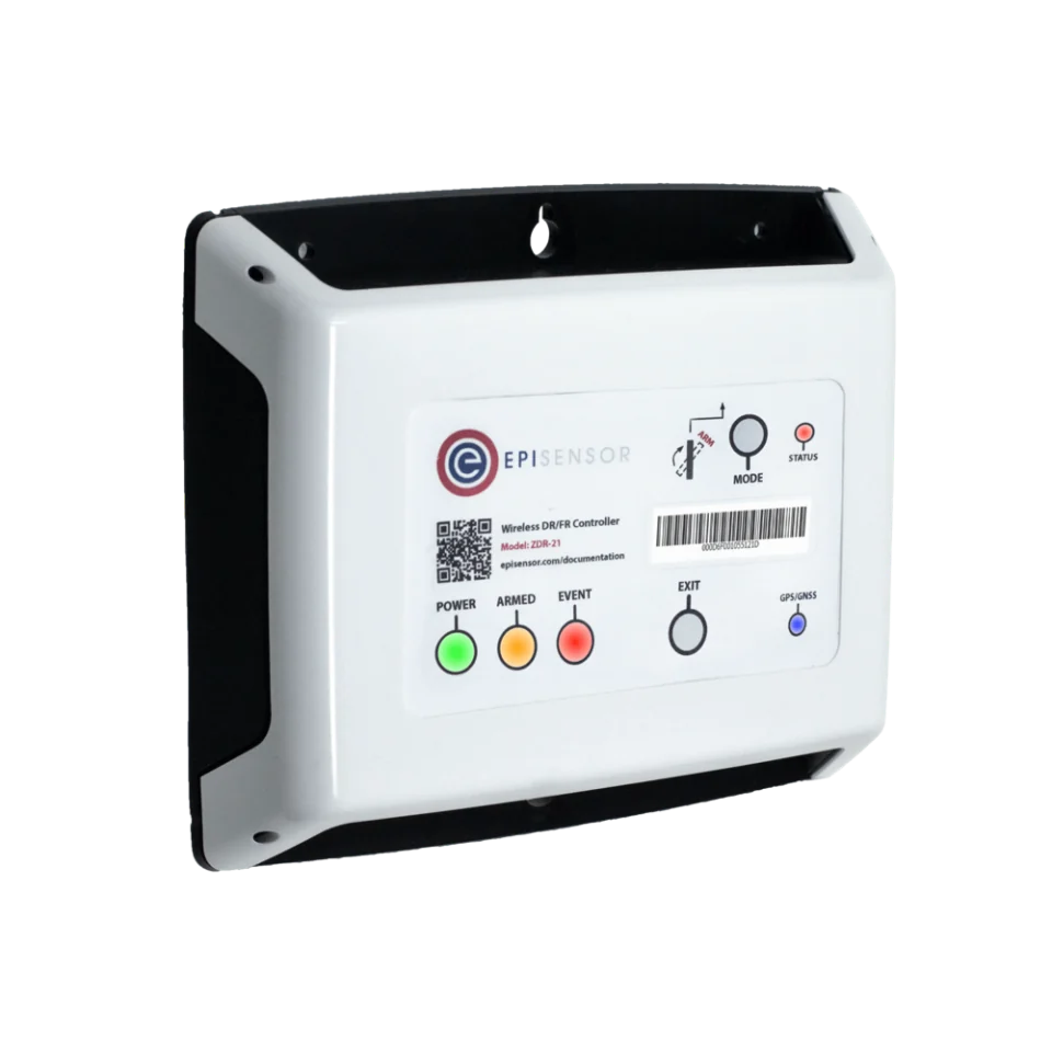


- Measure
- Point-of-connection power, battery AC power, state of charge, availability and temperature limits
- Good practice
- Event and rebound energy are measured against the programme's own baseline DOE
- Sensors
- ZDR-22, grid frequency sampled at 100 ms or better, 0.01 Hz resolution, 20 ms event recording Demand Response Controller datasheet
- On site
- ZGW-20 Gateway, BESS monitoring, dispatch records and onward telemetry Gateway datasheet
Hardware for battery flexibility telemetry
One controller at the connection for the fast response, one meter on the battery so its contribution can be separated, and the BMS for what the electricity cannot show.
Measures at the connection and sends a changing set point to the inverter over Modbus
1 per connection Class 0.5S metering included
- Choose the CT type: mini-CTs on existing 1 A or 5 A CTs, or Rogowski coils at 1 kA and 3 kA
Frequency sampled at 100 ms or better at 0.01 Hz, 20 ms event recording, GPS time sync, RS-485 Modbus RTU master for up to 4 devices
The battery's own AC power, separated from the rest of the site
1 per battery three-phase, 3 or 4 wire
- Choose the CT rating for the battery's AC connection: 120 A split-core, or 300 A, 1 kA and 3 kA Rogowski coils
Keeps the event record, the availability picture and the onward telemetry
1 per site up to 250 wireless devices
Where the BMS is on its own bus

Charge state, power limits, temperatures and alarms from the BMS or inverter
1 per bus up to 30 registers
What bounds a battery's dispatchable envelope
These measurements turn a battery’s rating into the capacity you can offer.
From field measurement to Edge
Each field signal reaches its named EpiSensor interface, reports through the site Gateway and is handled locally in Edge.
- Control
- Zigbee
- Wired
- Edge
- Platforms
| Position | What it tells you | Reference | Sensor |
|---|---|---|---|
| Point of connection | The change the grid actually saw, in one sign convention | Import positive and export negative, on matching interval boundaries Demand Response Controller datasheet | ZDR-22 (on this page), connection |
| Battery AC power | The battery's own contribution, separate from unrelated site load | Record whether auxiliary loads are inside the measurement Wireless 3-Phase Electricity Monitor datasheet | ZEM-65 (on this page), battery |
| State of charge and limits | How long a response can be sustained, and how much has to be kept back | The BMS state of charge is a model output, with its own reserve and uncertainty Modbus Interface datasheet | ZMB-31 (on this page) |
| Availability and protection | Whether the capacity can be offered at all right now | Alarms, temperature limits, contactor state and maintenance mode | ZMB-31 (on this page), status registers |
Record AC and DC power separately. Point-of-connection power includes the inverter’s losses and the site’s auxiliaries. Say which side of them each figure is on.
The BMS can refuse a set point. The battery management system owns its own protection. Record each refusal beside the request it answered.
Dispatch and event evidence in Edge
Record every dispatch with the request, the response and the data behind it.
- Availability before commitment
- A calculated sensor removes unavailable capacity from the offer: reserve, temperature limits, alarms and maintenance mode all subtract from it.
- Requested against achieved
- Every dispatch keeps both: what was asked for and what the meters measured, with the ramp between them.
- Withdraw when the data goes stale
- If the BMS data or a meter stops, the availability falls to zero rather than continuing from the last good reading.
- The event record leaves the site
- Interval data and events export over MQTT or HTTP to the programme's own telemetry, and stay on the Gateway as well.
Commissioning checks
Do these with the battery's commissioning engineer present, and before any capacity is offered.
-
Every meter agrees on direction
During a known charge and a known discharge, compare the connection, the battery meter and the inverter's own figures.
Pass when all three tell the same story in one sign convention, with the differences explained.
-
State of charge and limits are read correctly
Compare the values in Edge with the BMS display across a charge and a discharge.
Pass when the values and their units match, including the charge and discharge limits.
-
A dispatch is followed and recorded
Run an approved dispatch and record requested power, achieved power, ramp and acknowledgement.
Pass when the achieved power follows the request inside the agreed time, and the record shows both.
-
Loss of data withdraws capacity
Simulate stale BMS data and an unavailable inverter in turn.
Pass when availability falls to zero and the programme telemetry says so.
-
A full cycle is captured
Run a bounded event and its recovery while keeping every interval.
Pass when the whole window is in the record, including the energy state at the start and the end.
Limits of this measurement
Everything here sits outside the battery's own protection and the programme's own rules.
- External monitoring and dispatch must not bypass the battery management system, the inverter's protection or the site protection scheme.
- Nameplate power and energy are not continuously available flexibility once reserve, degradation, temperature and warranty conditions are applied.
- This guide does not approve grid-code compliance, fire safety, protection settings, market registration or settlement.
- Whether a measured reduction is a paid reduction is decided by the programme's baseline method, not by the meter.
Sources
- Measurement and verification for demand response (opens in a new tab) US Department of Energy and FERC
- Battery energy storage system evaluation method (opens in a new tab) (opens in a new tab) US Department of Energy FEMP
- Demand Response Controller datasheet (opens in a new tab) EpiSensor. Specifications, ranges and ordering codes.
Related
- OverviewDemand response and VPP
- CalculatorDemand response event calculator
- GuideDynamic frequency response services explained


Third-party devices for this application



More in the Device Directory: Energy meters (62), Current transformers (7)
Check a battery site against its programme's rules
An engineer can check what the registers give us, place the metering, and agree the availability rules.