Janitza UMG 96RM-E
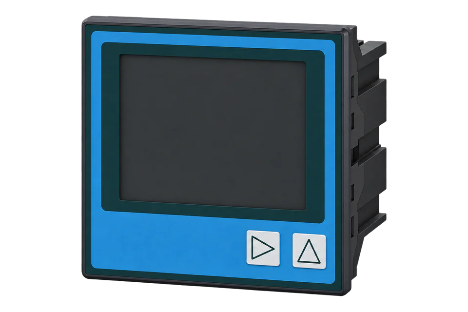
Panel-mounted power analyser
UMG 96RM-E is a panel power analyser with Ethernet, RS-485, external current-transformer inputs and additional residual-current monitoring. Its float and integer measurements already include the configured transformer ratios; applying a second ratio in Edge would overstate the readings.
- Modbus TCP
- Modbus RTU
Panel-mounted power analyser
Compatibility
Compatible through Modbus TCP or Modbus RTU
The manufacturer publishes the measurement register map and communication settings used by an Edge Modbus client.
UMG 96RM-E only. Best-effort starting map: 1.040.085.8.n, June 2024, from firmware 3.01/hardware release 104. Record the installed revision and compare the first values with the display. The non-E UMG 96RM has a different interface scope.
Connect it with
-
Modbus Interface ZMB-3XFrom €399 ex VAT Configure Modbus Interface
-
Gateway ZGW-20From €899 ex VAT Configure Gateway
-
Evaluation Gateway on a Raspberry Pi Edge with one device licensedFree Set up Evaluation Gateway on a Raspberry Pi


When the analyser is on the protected site network
- Modbus
- Edge
- Platforms
When its RS-485 slave interface is used
- Modbus
- Edge
- Platforms
Models
| Models | Interface | Route into Edge |
|---|---|---|
| UMG 96RM-E | Ethernet and RS-485; external 1 A / 5 A CT inputs | Use the published E-family map and compare voltage, current and power with the installed meter display. |
| 230 V supply option | 90–277 V AC, 50/60 Hz, or 90–250 V DC nominal supply range | Verify the actual auxiliary-supply label independently of the voltage measurement inputs. |
| 24 V supply option | 24–90 V AC/DC nominal auxiliary supply range | Do not infer the power-supply rating from the front panel model name alone. |
Specifications
The analyser measures three-phase power through external current transformers. It also has residual-current inputs, configurable digital I/O, a local display and internal recording memory. A current-transformer input is not a direct load connection: select the transformer secondary and set the ratio before judging the displayed engineering values.2
- Current inputs
- External ../1 A or ../5 A current transformers2
- Active energy accuracy
- Class 0.5 with ../5 A transformers; Class 1 with ../1 A transformers, as stated in the manual2
- Reactive energy
- Class 22
- Interfaces
- Ethernet and RS-485 Modbus RTU; Ethernet web server2
- Base register encoding
- Big-endian; alternate little-endian address bank at base + 327681
- Transformer scaling
- FLOAT and integer values include configured ratios; SHORT values require the corresponding transformer factor1
- Register update
- 200 ms, distinct from the selected network polling interval1
- Installation
- Panel mounted; -10 to +55 °C; IP40 front, IP20 rear, IP54 front with the specified seal2
Interface
Documented measurements and integration boundaries for UMG 96RM-E.
- Phase-to-neutral and phase-to-phase voltage, phase currents and calculated neutral current.
- Phase and total active, reactive and apparent power, power factor and frequency.
- Energy counters in documented float or integer formats; retain their declared units.
- Harmonics, averages, minimum/maximum values and time-stamped limits from the appropriate address blocks.
- Residual-current measurements when the additional inputs and suitable transformers are actually installed.
Assessment
UMG 96RM-E only. Best-effort starting map: 1.040.085.8.n, June 2024, from firmware 3.01/hardware release 104. Record the installed revision and compare the first values with the display. The non-E UMG 96RM has a different interface scope.
- InteroperabilityWell supported
- Published Ethernet/serial services and a versioned address list define functions, formats and alternate byte-order access.12
- AccuracySupported with conditions
- The manual states different active-energy classes for 5 A and 1 A CT secondaries and documents transformer-dependent measurements.12
- SecurityLimited
- A user password protects configuration access, but that does not establish encrypted or authenticated Modbus transport. Keep the measurement network controlled.2
- ReliabilitySupported with conditions
- The manual documents internal recording memory, a battery-backed clock and diagnostic functions; a client must still detect stale communications.2
- RuggednessSupported with conditions
- Panel protection and the -10 to +55 °C operating range are specified; rear terminals require a suitable enclosure.2
- ScalabilitySupported with conditions
- Ethernet and addressed serial access support multi-meter systems. The 200 ms register update does not imply every shared bus can poll that quickly.12
- LifecycleSupported with conditions
- The map identifies minimum firmware and hardware revisions, allowing an installation to retain a reproducible version contract.1
Setup
Read the manufacturer’s L1-N voltage address
The operating manual gives the FC03 request at decimal address 19000. Use the current address list to interpret its two-register FLOAT value.
- Function
- FC03 Read Holding Registers
- PDU start
- 19000 decimal, 0x4A38; use the physical address directly
- Length
- 2 registers, four data bytes
- Decode
- IEEE-754 float32, big-endian; V, multiplier 1, offset 0
- Independent vector
- A simulated 230.0 V value is 0x43660000, returned as words 0x4366, 0x0000.
- Request PDU
- 03 4A 38 00 02; the client adds the TCP header or RTU address and CRC
- Alternate bank
- The map documents little-endian access at base + 32768. This example uses the normal base address and must not also select that bank.
Acceptance: The operating manual’s abbreviated reply illustration is not a complete consistent FLOAT frame; this guide uses its request and the address list’s data definition, with an independently calculated test vector. Confirm actual live voltage against the display before adding other measurements.
-
Check the hardware, firmware and CTs
Record the E suffix, hardware release and firmware, then check current and voltage transformer ratios against the installed instruments. Never open an energised CT secondary for a communications check.
-
Choose the transport explicitly
For Ethernet, use Modbus TCP framing on port 502. Port 8000 is a separate RTU-over-Ethernet service. For RS-485, match the meter address and supported speed with 8 data bits and no parity; keep one master on the bus.
-
Read the documented voltage address
Read FC03, PDU address 19000 (0x4A38), length two registers. Decode big-endian IEEE-754 float32 in volts with multiplier 1. Use the independent vector below to test the software decoder.
-
Avoid applying transformer ratios twice
The float and integer lists already include the configured ratios. Use multiplier 1 for the documented float voltage/current units. The SHORT lists behave differently and require the corresponding ratio, so do not mix formats within an imported point definition.
-
Expand to current, power and energy
Use FC03, two registers per value, in the normal big-endian FLOAT bank: L1 current 19012 (A), total active power 19026 (W), frequency 19050 (Hz), total consumed active energy 19068 (Wh) and total delivered active energy 19076 (Wh). For power, the PDU is 03 4A 52 00 02. Synthetic bytes 46 43 50 00 decode to 12500 W; 42 48 00 00 decode to 50 Hz. Multiplier 1 applies to these FLOAT values; do not apply the CT ratio again. Divide W or Wh by 1000 only when presenting kW or kWh. Keep consumed and delivered counters separate. Compare current, power, frequency and counter direction with the display, timestamp samples and detect missing or stale data.
Common questions
- Why is my current too high by the CT ratio?
- Check whether the point comes from the FLOAT or integer address list. Those values already include the configured transformer ratios. Multiplying again in Edge double-scales the current. SHORT measurements require different treatment.1
- Is port 8000 another Modbus TCP port?
- The manual lists 502 for Modbus TCP and 8000 for Modbus RTU over Ethernet. These use different framing, so changing only the port in a TCP client does not make it an RTU-over-Ethernet client.2
- Can this map be used on every UMG 96RM?
- Use the UMG 96RM-E address list as a best-effort starting point and compare the first values with the display. Its documented scope is firmware 3.01 onward/hardware release 104. The E suffix matters because the other 96RM variants have different interfaces.1
Related devices

Sources
- UMG 96RM-E Modbus address list, 1.040.085.8.n, June 2024 (opens in a new tab) (PDF)
- UMG 96RM-E operating manual (opens in a new tab) (PDF)
Further reading
Product names and trademarks belong to their owners. Publication does not imply endorsement or a commercial relationship.