Lovato DME D330
Power and energy meter
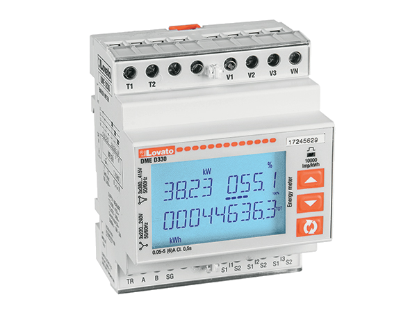
DMED330 is a four-module meter for three-phase systems with or without neutral. It uses external CTs, an isolated serial interface and a programmable tariff input. Edge can read local electrical measurements over Modbus RTU; the standard DMED330 and the separate MID version must be identified correctly.
Compatibility
Compatible with EpiSensor Edge over Modbus RTU
Lovato documents the built-in serial interface, read functions, register lengths and integer scaling for DMED330.
Standard DMED330 with CT insertion. Use operating manual I444IGB09_22 and the DMED330 column of protocol I315IGB08_22. Confirm the installed code, firmware, CT ratio and wiring, then compare one read with the display before extending the poll.
Connect it with
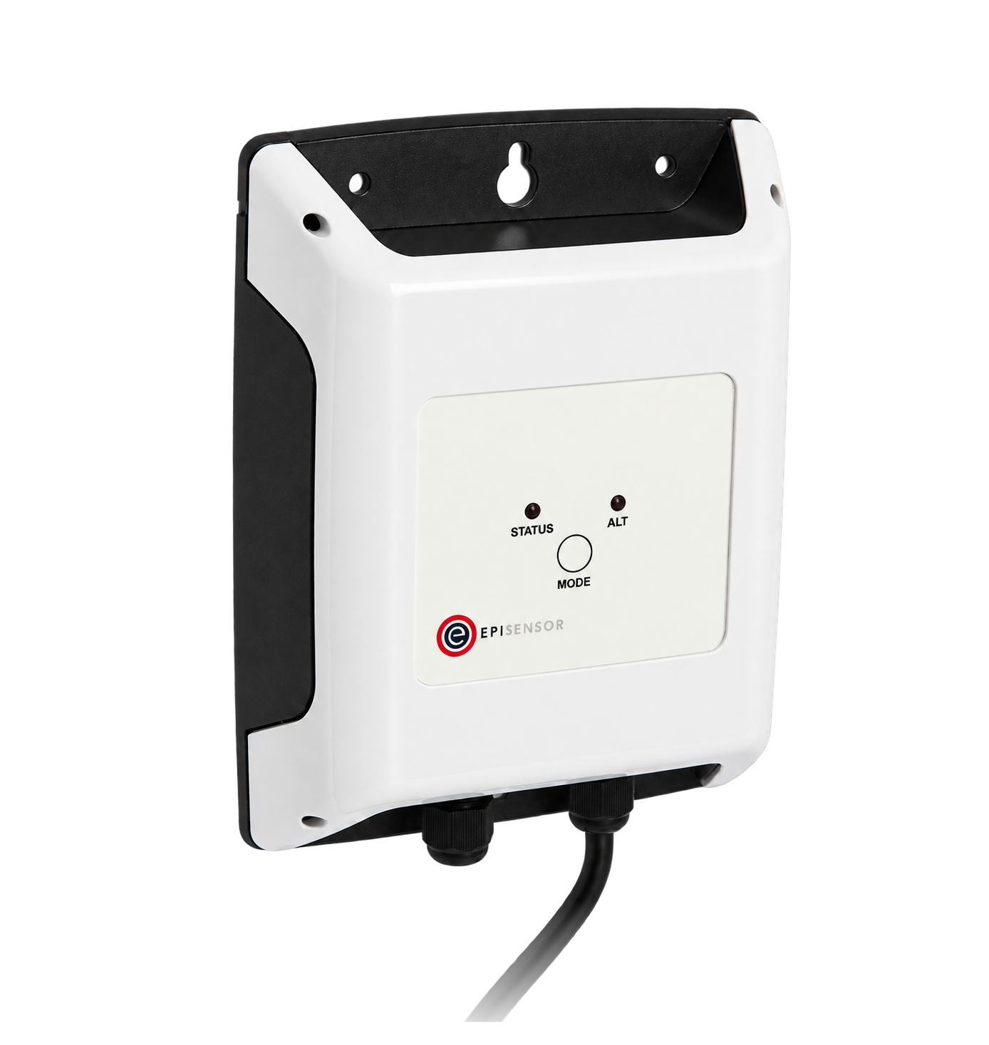
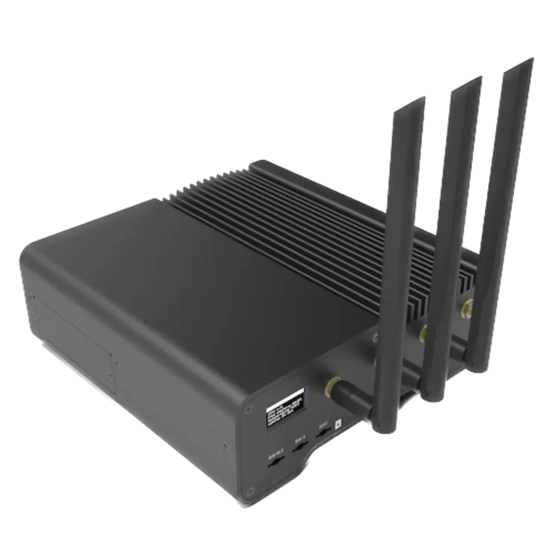
For the built-in DMED330 serial interface
- Modbus
- Edge
- Platforms
Models
| Models | Interface | Route into Edge |
|---|---|---|
| DMED330 | CT-connected, non-expandable DIN-rail meter with isolated RS-485 and a tariff/control input. | The serial port is built in; an external serial interface connects it to the Gateway. |
| DMED330MID / DMED310T2 / DMED320 | Separate ordering variants or models within the shared communications manual. | Use the DMED330 applicability column and its scales. Do not infer MID approval or an Ethernet port from the family manual. |
Specifications
Use the full I444 operating manual for settings and limits. I446 is the separate quick installation document still linked by Lovato. The meter is powered from its measurement voltages; its tariff input is a separate control circuit.13
- Current inputs
- CT secondary configurable for 1 A or 5 A; rated current 5 A, maximum 6 A.1
- Measurement supply
- Rated 220–240 VAC L-N / 380–415 VAC L-L; operating range 187–264 VAC L-N / 323–456 VAC L-L, with or without neutral.1
- Energy accuracy
- Active energy class 0.5S to IEC/EN/BS 62053-22. CT and installation errors are additional.1
- Serial configuration
- M07 selects node, 1200–115200 bit/s, data format, one/two stop bits and protocol. Defaults are node 01, 9600 bit/s, 8N1 and Modbus RTU.1
- Installation envelope
- Four DIN modules, 71.6 mm wide; indoor −25 to +55 °C and humidity below 80%. Front IP40, terminals IP20; the manual requires an enclosure rated at least IP51.1
Interface
Documented measurements and integration boundaries for DME D330.
- L1 voltage: printed 0002H, PDU 0001H, two unsigned registers divided by 100 for V. L1 current: printed 0008H, PDU 0007H, two unsigned registers divided by 10000 for A.
- L2 active power: printed 0016H, PDU 0015H, two signed registers divided by 100 for W. Frequency: printed 0032H, PDU 0031H, two unsigned registers divided by 1000 for Hz on DMED330.
- The table 4 energy totals, including import/export active energy at printed 1B20H/1B24H, use four registers each. Edge’s Modbus client does not read these 64-bit values. Keep those totals on the meter display instead of taking half a counter.
Assessment
Standard DMED330 on its built-in isolated serial port, using the DMED330 model column.
- InteroperabilityWell supported
- The public Modbus RTU table specifies read functions, address conversion, widths and model applicability for the built-in interface.12
- AccuracySupported with conditions
- CT ratio and wiring settings determine the electrical reading. The manual specifies class 0.5S active energy, but four-register energy totals exceed Edge’s Modbus read width.12
- SecurityLimited
- Two password levels protect settings and a programmable input can lock them. Plain Modbus RTU still needs restricted physical and network access; use a read-only monitoring configuration.12
- ReliabilitySupported with conditions
- Measurement voltages supply the device. The manual describes retained HI and maximum-demand values and an EEPROM configuration backup. Maintain the documented supply and installation conditions.1
- RuggednessSupported with conditions
- The manual specifies −25 to +55 °C, humidity below 80%, 15g shock and 0.7g vibration tests. Indoor installation needs an enclosure rated at least IP51 around the IP40 front/IP20 terminals.1
Setup
Reproduce the manufacturer’s L2-power example
Protocol I315IGB08_22 pages 3–4 gives a complete FC04 request and answer; table 2 confirms the DMED330 signed two-word quantity.
- Function
- FC04 Read Input Registers
- PDU address and length
- 0016H − 1 = 0015H = 21 decimal; 2 registers
- Request PDU
- 04 00 15 00 02
- Manufacturer example data
- 00 01 FB 00 → signed 129792 / 100 = 1297.92 W = 1.29792 kW
- Acceptance
- Compare with instantaneous L2 active power on the meter display, including the sign and unit.
Acceptance: These bytes reproduce Lovato’s documentation example, not an EpiSensor device capture. The RTU client adds its configured slave address and CRC. Do not reinterpret the integer as FLOAT32.
-
Confirm the installed CT circuit
Have the authorised installer check CT primary/secondary settings P01.01/P01.02 and connection type P01.05. Wiring changes require the isolation and CT-secondary short-circuiting precautions in the manufacturer’s manual.
-
Match the serial parameters
Read M07 parameters P07.01–P07.05 and match them in Edge. Use the RTU setting and an 8-bit data format; the manual reserves 7-bit formats for ASCII.
-
Translate the table address once
For L2 active power, printed address 0016H becomes PDU 0015H, decimal 21. Read two registers with FC04. The manual allows FC03 and FC04 for its measurement table; this check follows its FC04 example.
-
Decode the signed value and compare
Read the two words in the manufacturer’s order as one signed 32-bit integer. Divide by 100 for W, then by 1000 for kW. Compare with the simultaneous instantaneous L2-power display. Apply the DMED330 frequency divisor of 1000, not the 310/320 divisor of 100.
Common questions
- Are I444 and I446 competing revisions?
- They are different documents for DMED330. The product page links I444IGB09_22 as the full operating manual and I446IGB09_17 as the quick installation manual. Use I444 for the complete parameter and technical tables.13
- Why is a frequency value ten times too large?
- The shared map specifies Hz/100 for DMED310T2 and DMED320, but Hz/1000 for DMED330. Use the D330-specific scale and retain both words.2
Related devices

Sources
- DMED330 operating manual, I444IGB09_22 (opens in a new tab) (PDF)
- DME Modbus communication protocol, I315IGB08_22 (opens in a new tab) (PDF)
- DMED330 official product record and document list (opens in a new tab)
Further reading
Product names and trademarks belong to their owners. Publication does not imply endorsement or a commercial relationship.