Janitza UMG 96-PA
Panel-mounted power analyser
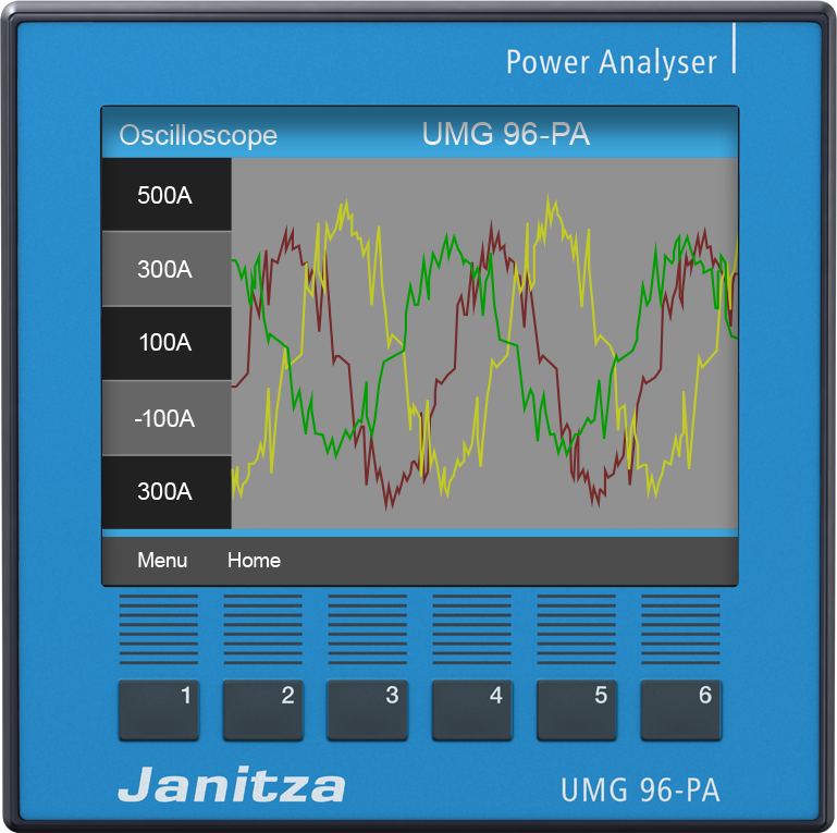
The UMG 96-PA is a 96 × 96 mm front-panel power analyser for ../1 A or ../5 A current transformers, with a colour display, 8 MB of data memory and an RS-485 Modbus RTU port. It comes as the UMG 96-PA with a 230 V or 24 V supply option and as the MID-certified UMG 96-PA-MID+; both use the same measurement table. Janitza prints the addresses as literal decimal PDU addresses and returns each measurement as a two-register IEEE-754 Float, big-endian, already scaled by the configured transformer ratios.
Compatibility
Compatible with EpiSensor Edge over Modbus RTU
Janitza documents Modbus RTU on the UMG 96-PA's RS-485 port, gives the FC03 request for decimal address 19000 and publishes a Float measurement table with units. This is documented compatibility, without a physical Edge test.
UMG 96-PA (item 52.32.001, 230 V supply; 52.32.002, 24 V supply) and UMG 96-PA-MID+ (52.32.004) on their own RS-485 port, using the Modbus table in user manual 2.061.059.4.a (11/2025, firmware 3.54 and later) as a best-effort starting point, with the byte-order and transformer rules of the firmware 2.0 address list. Compare the first read with the display. Ethernet through the 96-RCM-E module and the module's own measurements are outside this guide. Read-only monitoring.
Connect it with
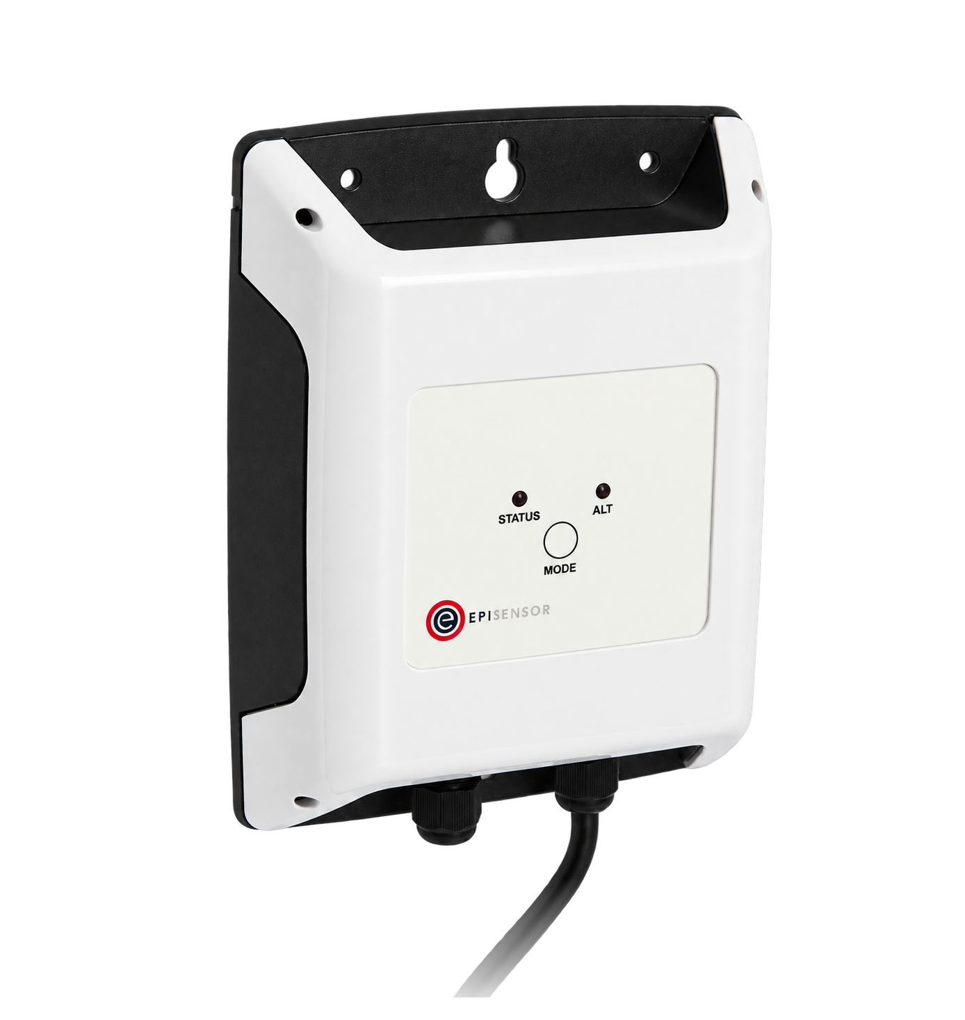
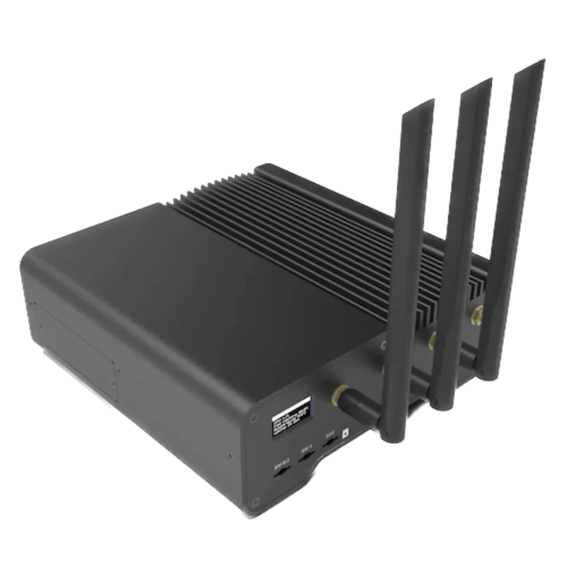
For the analyser's own three-pole RS-485 plug (A, B, Data GND)
- Modbus
- Edge
- Platforms
Models
| Models | Interface | Route into Edge |
|---|---|---|
| UMG 96-PA (items 52.32.001 and 52.32.002) | 230 V option: 90 to 277 V AC or 90 to 250 V DC supply. 24 V option: 24 to 90 V AC/DC. RS-485 Modbus RTU; external ../1 A or ../5 A CTs | Read the 19000 Float table with FC03 on the serial path. |
| UMG 96-PA-MID+ (item 52.32.004) | MID-certified version (2014/32/EU) with the 230 V supply option only; password protected ex works; the same RS-485 port and table | Same read path and addresses. Configuration needs the device password; keep the poll read-only. |
| UMG 96-PA and UMG 96-PA-MID with firmware 1.12 or 2.x | Older address lists 2.061.029.1 and 2.061.028.2.c; they give 8 data bits, no parity and 2 stop bits from the analyser | Addresses 19000 to 19098 are identical in all three documents. Match the serial framing to the installed device. |
| With the 96-RCM-E (formerly 96-PA-RCM-EL) module | Adds Ethernet, a fourth current input, residual current inputs and temperature measurement | Use the module's own documentation before choosing Modbus TCP or reading its measurements; this guide covers the base RS-485 port. |
Specifications
The UMG 96-PA is a modular panel analyser: the base device measures three voltages and three CT currents, logs to 8 MB of memory and talks Modbus RTU on RS-485, and a plug-in module adds Ethernet, a fourth current input, residual current and temperature. The UMG 96-PA-MID+ adds MID certification, a logbook of legally relevant changes and sealable terminal covers, and keeps the functions of the base device.14
- Versions
- UMG 96-PA, item 52.32.001 (230 V supply option) and 52.32.002 (24 V supply option). UMG 96-PA-MID+, item 52.32.004 (230 V supply option).14
- Supply
- 230 V option: 90 to 277 V AC (50/60 Hz) or 90 to 250 V DC. 24 V option: 24 to 90 V AC or DC, UMG 96-PA only. Maximum 4.5 VA / 2 W.1
- Voltage measurement
- Three-phase four-wire up to 417 V L-N / 720 V L-L (IEC); 600 V CAT III. The MID+ certified range is 3 × 57.7/100 V to 3 × 289/500 V.1
- Current measurement
- Three inputs for external ../1 A or ../5 A CTs; nominal 5 A, measuring range 0.005 to 6 A (MID+: 0.002 to 6 A).1
- Accuracy
- Active energy class 0.2S with ../5 A CTs and 0.5S with ../1 A CTs (IEC 62053-22); reactive energy class 1. MID+: class B to MID 2014/32/EU.1
- RS-485
- Modbus RTU server on a three-pole plug (A, B, Data GND). Device address 1 to 247 (default 1). 9600, 19200, 38400, 57600 or 115200 bit/s (default 115200). 8 data bits; odd or even parity with 1 stop bit, or no parity with 1 or 2 stop bits (default no parity, 1 stop bit).1
- Bus
- Up to 32 devices per segment, repeaters beyond that; 1200 m at 38.4 kbit/s. No built-in termination: fit 120 Ω, 1/4 W at each end of the segment.1
- Other interfaces
- Three digital inputs (pulse counter, tariff switching or clock synchronisation), three digital outputs and one 0 to 20 mA analogue output.1
- Mounting and environment
- 96 × 96 mm front-panel device, about 250 g. -10 to +55 °C in operation, 0 to 75% RH non-condensing. IP40 front, IP54 front with seal, IP20 rear; indoor or weather-protected cabinets.1
Interface
Documented measurements and integration boundaries for UMG 96-PA.
- Addresses are literal decimal PDU addresses: 19000 is sent as 4A 38. Read every point with FC03, two registers, IEEE-754 Float32, high byte first.
- L1-N, L2-N and L3-N voltage at 19000, 19002 and 19004; L1-L2, L2-L3 and L3-L1 voltage at 19006, 19008 and 19010: V.
- L1, L2 and L3 current at 19012, 19014 and 19016; vector sum I1+I2+I3 at 19018: A.
- L1 to L3 active power at 19020, 19022 and 19024, total active power at 19026: W.
- Total apparent power at 19034 (VA) and total reactive power at 19042 (var), each after its L1 to L3 values.
- Fundamental power factor (cos φ) for L1, L2 and L3 at 19044, 19046 and 19048; frequency at 19050 (Hz); rotating field at 19052 (1 right, 0 none, -1 left).
- Active energy L1..L3 consumed, tariff 1, at 19068 and active energy L1..L3 delivered at 19076: Wh.
- Total apparent energy at 19084 (VAh) and total reactive energy at 19092 (varh).
- Janitza marks 19054 to 19058 and 19086 to 19090 as assigned differently from other UMG devices. Do not copy those points from another UMG template.
- Every Float value already includes the configured CT and VT ratios. Add 32768 to an address only to read the same value little-endian.
Assessment
UMG 96-PA (item 52.32.001, 230 V supply; 52.32.002, 24 V supply) and UMG 96-PA-MID+ (52.32.004) on their own RS-485 port, using the Modbus table in user manual 2.061.059.4.a (11/2025, firmware 3.54 and later) as a best-effort starting point, with the byte-order and transformer rules of the firmware 2.0 address list. Compare the first read with the display. Ethernet through the 96-RCM-E module and the module's own measurements are outside this guide. Read-only monitoring.
- InteroperabilityWell supported
- Janitza documents Modbus RTU on RS-485, the supported function codes, an FC03 request example with the literal address, a Float table with units and a separate little-endian bank. The 19000 table is identical across the firmware 1.12, 2.0 and 3.54 documents.123
- AccuracySupported with conditions
- Three-phase voltage, current, power, power factor and consumed and delivered energy, with active energy class 0.2S on ../5 A CTs. Accuracy depends on the installed CTs and VTs and on correctly configured ratios.1
- SecurityNot yet assessed
- The device has a configuration password, set ex works on the MID+, but the manual does not describe access control on the Modbus port, which accepts documented write functions.1
- ReliabilitySupported with conditions
- Modbus values update every 200 ms, a battery-backed clock and 8 MB of memory keep local records, and energy values are saved to non-volatile memory every five minutes, so a supply failure can interrupt recording for up to five minutes. Treat failed reads as missing data.12
- RuggednessSupported with conditions
- Rated -10 to +55 °C, IP40 front (IP54 with seal) and IP20 rear, impact resistance IK07, for stationary indoor or weather-protected cabinets.1
- ScalabilitySupported with conditions
- Device addresses 1 to 247, up to 32 devices per segment before a repeater and 1200 m at 38.4 kbit/s. Polling more points per device lengthens each cycle on a shared bus.1
Setup
Read L1-N voltage from decimal address 19000
Section 18.2 of user manual 2.061.059.4.a lists voltage L1-N at address 19000, format float, read-only, unit V, and section 13.13.1 gives the FC03 request for it. Use that table as the starting point and compare the result with the display.
- Request
- 01 03 4A 38 00 02 53 DE: device address 1, FC03, address 19000 (0x4A38), two registers, RTU CRC.
- Address convention
- Janitza's table addresses are literal zero-based PDU addresses: the manual's own example sends 19000 as 4A 38. A client that numbers registers from one shows it as 19001 (or 419001 in 4x notation). Do not subtract one.
- Synthetic response
- 01 03 04 43 66 00 00 0F A8: byte count 04, data 43 66 00 00.
- Decode
- High byte before low byte (Motorola format), first register first: 0x43660000 as an IEEE-754 Float32 is 230.0 V. No multiplier applies, and the configured VT ratio is already included.
- Alternate bank
- 19000 + 32768 = 51768 (0xCA38) returns the same value little-endian. Use that bank only with a little-endian decoder.
- Acceptance
- Keep the point when it agrees with L1-N voltage on the display at the same time. If it does not, check the device address, data frame and address convention before adding more points.
Acceptance: The response bytes are a synthetic decoder check, not a captured reply. The manual's abbreviated reply example shows a single 16-bit value; a complete Float read returns four data bytes, as above.
-
Identify the analyser
Read UMG 96-PA or UMG 96-PA-MID+ from the front and record the item number, the supply option and the firmware version shown in the System window of the configuration menu. Note whether a 96-RCM-E module is fitted.
-
Read the communication settings
The Communication window in the configuration menu shows the device address, baud rate and data frame. The defaults are address 1, 115200 bit/s, 8 data bits, no parity and 1 stop bit. Enter the same values in the Edge serial client; the MID+ asks for its password before the configuration menu opens.
-
Wire the RS-485 pair
Connect A, B and Data GND on the three-pole plug with twisted, shielded cable, and give each device on the segment its own address. The analyser has no internal termination: fit a 120 Ω, 1/4 W resistor at both ends of the segment, and earth the shield at the cabinet entry rather than on Data GND.
-
Make one voltage read
Send FC03 to decimal address 19000 (0x4A38) for two registers and decode the Float32 high byte first, as in the worked read below. Compare the result with L1-N voltage on the display.
-
Add the points you need
Add current at 19012, total active power at 19026 and frequency at 19050 from the same table, then the energy counters at 19068 and 19076. Keep consumed and delivered energy separate, and keep FC06, FC16 and FC23 writes out of the polling configuration.
Common questions
- Is 19000 the register number or the address on the wire?
- It is the address on the wire. The manual's request example sends 19000 as start address 4A 38, so enter 19000 in a client that takes zero-based PDU addresses and 19001 in one that numbers registers from one.1
- Do I need to multiply by the CT ratio?
- Not for the Float values. Janitza's address lists state that Float values include the configured transformer factors, while values in the short format do not. The integer energy section is an exception: it states that those values exclude CT and VT ratios. Read the Float table and compare current and power with the display under load.23
- Which energy register is total consumption?
- The 19000 table gives active energy consumed at 19068, labelled tariff 1, and delivered energy at 19076, both in Wh. When the analyser switches between two tariffs, the full address list also has active energy sum consumed at 5006, with HT and NT sums at 5014 and 5022 and the delivered sum at 5078. That block prints no unit, so compare it with 19068 and the display before using it.12
- Can I reuse a UMG 96RM-E point list?
- Mostly, with care. The main 19000 Float table follows the same pattern, but Janitza marks 19054 to 19058 and 19086 to 19090 as assigned differently from other UMG devices. Build the point list from the UMG 96-PA table rather than a template made for another model.1
Related devices
Sources
- UMG 96-PA / UMG 96-PA-MID+ user manual and technical data, as of firmware 3.54, doc. no. 2.061.059.4.a (11/2025) (opens in a new tab) (PDF)
- UMG 96-PA / UMG 96-PA-MID Modbus address list and formulary from firmware 2.0, doc. no. 2.061.028.2.c (06/2021), German edition (opens in a new tab) (PDF)
- UMG 96-PA / UMG 96-PA-MID Modbus address list and formulary up to firmware 1.12, doc. no. 2.061.029.1 (08/2018) (opens in a new tab) (PDF)
- Modular energy measurement devices, UMG 96-PA series brochure, doc. no. 2.500.135.7 (04/2022) (opens in a new tab) (PDF)
Further reading
Product names and trademarks belong to their owners. Publication does not imply endorsement or a commercial relationship.