KBR multimess F96-TFT
Panel-mounted power analyser
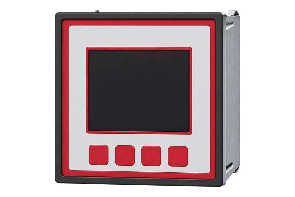
The multimess F96-TFT is KBR's 96 x 96 mm panel analyser for three-phase networks. It reads voltage, current, power, power factor, harmonics to the 63rd and four energy counters (consumption and recovery, high and low tariff) through external x/1 A or x/5 A current transformers. The interface depends on the device type: the MS and ESMS types have an RS-485 port that speaks Modbus RTU or ASCII once the bus protocol is switched from KBR eBus to Modbus, and the MT type has Ethernet with Modbus TCP. KBR's data point description lists every value as a 32-bit IEEE float read with function 04, at the table address minus one.
Compatibility
Compatible with EpiSensor Edge over Modbus RTU or Modbus TCP
The multimess F96-TFT is compatible with EpiSensor Edge over Modbus RTU on the RS-485 port of the MS and ESMS device types, read through a ZMB-31 Modbus Interface or a Gateway serial port, and over Modbus TCP on the MT device type. KBR publishes the Modbus data point description with addresses, word counts, data formats and units in chapter 10 of the manual.
multimess F96-TFT device types MS, ESMS and MT (series -5), read with the data point description in manual 26195_EDEBDA0297-3724-1_EN V5.00. The ET and ESET-GW types speak KBR eBus only and the base type has no interface. Site check: read network frequency at table address 0x00B0 and compare it with the display. Read-only monitoring: no writes to the device settings from 0xD002 or the commands from 0xF001.
Connect it with


For an MS or ESMS type in a panel door where a wireless link avoids running a data cable back to the Gateway
- Modbus
- Wireless
- Edge
- Platforms
When the Gateway sits near the panel, or several meters share one wired RS-485 bus
- Modbus
- Edge
- Platforms
For the MT device type, which has the Ethernet port with Modbus TCP
- Modbus
- Edge
- Platforms
Models
| Models | Interface | Route into Edge |
|---|---|---|
| multimess F96-2-TFT-MS-2RO1DO-US_-5 (article 23430 with US1 supply, 24006 with US5) | RS-485 with Modbus RTU or ASCII, 2 relay outputs, 1 pulse output | Read over Modbus RTU through a ZMB-31 or a Gateway serial port with function 04. |
| multimess F96-0-TFT-ESMS-1DO-US_-5 (23424, 24341) and F96-2-TFT-ESMS-2RO1DO-US_-5 (23426, 24002) | RS-485 for KBR eBus or Modbus RTU/ASCII; the -2 type adds 2 relay outputs | Switch the bus protocol from KBR eBus to Modbus in the Bus menu, then read over Modbus RTU. |
| multimess F96-2-TFT-MT-2RO1DO-US_-5 (23427, 24003) | Ethernet (TCP/IP) with Modbus TCP, 2 relay outputs, 1 pulse output | Read over Modbus TCP from the Gateway with the same data point table and function 04. |
| multimess F96-2-TFT-ET-2RO1DO-US_-5 and F96-2-TFT-ESET-2RO1DO-GW-US_-5 | KBR eBus TCP, or KBR eBus RS-485 and eBus TCP with gateway function; no Modbus | KBR eBus is not an Edge route. Order an MS, ESMS or MT type for a Modbus read. |
| multimess F96-0-TFT-1DO-US_-5 (23423, 23431) | No communication interface; 1 pulse output | No Modbus read. The S0 pulse output is outside this guide. |
Specifications
The multimess F96-TFT is a three-phase panel analyser for a 92 x 92 mm cut-out. It measures through external current transformers and voltage transformers where needed, logs daily energy values and period values, and records voltage dips. KBR states measurement accuracy to DIN EN 61557-12 and power quality to DIN EN 61000-4-30.12
- Device types
- Base, ESMS, MS (Modbus RS-485), MT (Modbus TCP), ET and ESET-GW (KBR eBus only), each with US1 or US5 supply.2
- Current inputs
- 3 x 0.01 A ... 1 A ... 1.2 A AC or 3 x 0.05 A ... 5 A ... 6 A AC through current transformers; at most 0.3 VA per input at 6 A.1
- Voltage inputs
- 3 x 5 V ... 100 V ... 120 V AC or 3 x 20 V ... 500 V ... 600 V AC; higher voltages through voltage transformers.1
- Power supply
- US1: 100 to 240 V +/- 10% AC/DC, 50/60 Hz, 8 VA, 4 W. US5: 22.5 to 64 V +/- 10% AC/DC, 8 VA, 4 W.12
- Modbus RTU
- RS-485 on terminals 90, 91 (A) and 92 (B); 4800, 9600 or 19200 baud with even, odd or no parity; factory setting 19.2 kBaud, even parity, 8 data bits, 1 stop bit; address 1 to 247 set on the device.1
- Accuracy (DIN EN 61557-12)
- Voltage and phase current class 0.5, frequency class 0.02, total active, reactive and apparent power class 1.1
- Housing
- 96 x 96 x 65 mm, cut-out 92 x 92 mm; front IP 40 (IP 51 with seal), terminals IP 20; 300 to 350 g depending on the option board.1
- Environment
- Operating -5 to +55 °C, storage -25 to +70 °C, 5 to 95% humidity non-condensing, up to 2000 m.1
Interface
Documented measurements and integration boundaries for multimess F96-TFT.
- KBR lists every data point with a table address and the note that, in accordance with the Modbus definition, the required address must be set to -1 in the request. Network frequency at table address 0x00B0 is sent as 0x00AF. KBR's own example reads active power L1 at 0x0020 by sending 00 1F.
- Measured values are read with function 04 (Read Input Registers). The supported commands are 0x02, 0x04, 0x06, 0x10 and 0x2B; function 03 is not listed, so set the Edge point to input registers.
- Each measured value is a 32-bit IEEE 754 float in two registers. KBR transmits the byte holding the sign bit first, so the lower-addressed register is the high word. Device setting 0xD02C reverses the float byte order when set to 0; leave it at 1.
- Phase voltages L1-N, L2-N and L3-N at 0x0002, 0x0004 and 0x0006 and line voltages at 0x0008, 0x000A and 0x000C, in V. Phase currents at 0x000E, 0x0010 and 0x0012 and their average values at 0x0014 to 0x0018, in A.
- Per-phase apparent power at 0x001A to 0x001E (VA), active power at 0x0020, 0x0022 and 0x0024 (W) and reactive power at 0x0026 to 0x002A (var). cos phi per phase at 0x002C to 0x0030 and power factor per phase at 0x0032 to 0x0036.
- Network frequency at 0x00B0 (Hz), neutral conductor current at 0x00B2 (A), total active power at 0x00B6 (W), total reactive power at 0x00B8 (var), total apparent power at 0x00BA (VA) and total power factor at 0x00BC.
- Voltage THD L1 to L3 at 0x0038 to 0x003C and odd voltage harmonics from the 3rd to the 19th from 0x003E, in %; total harmonic current per phase at 0x0074 to 0x0078 and current harmonics from 0x007A, in A.
- Energy meter readings as floats in Wh or varh: active energy consumption high tariff at 0x02C6 and low tariff at 0x02C8, reactive consumption at 0x02CA and 0x02CC, active recovery at 0x02F0 and 0x02F2 and reactive recovery at 0x02F4 and 0x02F6. The active tariff index is at 0x02EE.
- A 32-bit float holds about seven significant digits, so an energy register above 16,777,216 Wh no longer resolves single watt-hours. KBR also publishes the same counters as 64-bit doubles from 0xE002 (four registers each), which Edge's Modbus client does not read; use the float registers.
- Maximum and minimum values with their timestamps follow from 0x00C6, and period values for the demand interval from 0x1002. Error state is at 0x00C2 and device time at 0x00C4 (unsigned long, seconds since 1 January 1970 in standard time).
- Writes: device settings from 0xD002 (transformer ratios, tariffs, counter preset values) use function 0x10, and commands from 0xF001 (device reset, max and min reset, relay switching) use function 0x06. Keep them out of a monitoring poll.
Assessment
multimess F96-TFT device types MS, ESMS and MT (series -5), read with the data point description in manual 26195_EDEBDA0297-3724-1_EN V5.00. The ET and ESET-GW types speak KBR eBus only and the base type has no interface. Read-only monitoring: no writes to the device settings from 0xD002 or the commands from 0xF001.
- InteroperabilityWell supported
- KBR documents the supported Modbus functions, the address offset, the float byte order and every data point with address, length, unit and format, with worked RTU and ASCII examples.1
- AccuracySupported with conditions
- Accuracy classes to DIN EN 61557-12 are stated (voltage and current 0.5, total active power 1); system accuracy also depends on the CTs and their configured ratio.1
- SecurityNot yet assessed
- The manual recommends changing the factory IP address and password-protecting LAN devices. The Modbus description also defines setting writes (0x10) and commands (0x06).1
- ReliabilitySupported with conditions
- An error state register at 0x00C2 and an adjustable response-time factor at 0xD02A are documented; treat failed reads as missing data.1
- RuggednessSupported with conditions
- Operating -5 to +55 °C, humidity, altitude and IP 40 front (IP 51 with seal), IP 20 terminals are documented for panel installation.1
- ScalabilitySupported with conditions
- Up to 32 devices per RS-485 bus, or up to 1000 with repeaters, and Modbus addresses 1 to 247 are stated; the poll schedule and baud rate (at most 19.2 kBaud) set the practical limit.1
- LifecycleNot yet assessed
- The product page lists the current -5 device types with article numbers.2
Setup
First read: network frequency at table address 0x00B0
This uses the Modbus data point description in chapter 10 of KBR manual 26195_EDEBDA0297-3724-1_EN (V5.00). Network frequency at table address 0x00B0 is a float in two registers, unit Hz, read with function 04 at the table address minus one.
- Function
- FC04, read input registers. Function 03 is not in KBR's list of supported commands.
- Address
- Table 0x00B0 (176 decimal). Send 0x00AF (175), as KBR's own note requires the address minus one in the request.
- Request
- 01 04 00 AF 00 02 41 EA: Modbus address 1, FC04, address 0x00AF, two registers, RTU CRC.
- Synthetic response
- 01 04 04 42 48 00 00 6F EA: four data bytes, sign byte first.
- Decode
- IEEE 754 float, high word first: 0x42480000 = 50.0 Hz.
- Acceptance
- Matches the frequency on the display. A value near 2.38E-41 (0x00004248) means the words are swapped (check setting 0xD02C); an exception 01 means function 03 was sent instead of 04.
Acceptance: The response bytes are a synthetic decoder check, not a captured meter reply. Keep the point when a real reply agrees with the display, then add the remaining points with the same function, data type and address offset.
-
Check the device type on the nameplate
Read the type designation. MS and ESMS have an RS-485 port for Modbus RTU, MT has Ethernet with Modbus TCP. ET, ESET-GW and the base type have no Modbus interface.
-
Switch the bus protocol to Modbus
In Extra, Setup, Basic para (2), Bus, change the protocol from KBR eBus to Modbus and save; the device reboots. Then set the Modbus address and the RTU or ASCII mode, baud rate and parity. KBR's factory setting is 19.2 kBaud, even parity, 8 data bits, 1 stop bit.
-
Wire the RS-485 line
Connect A to terminal 91, B to terminal 92 and the reference to terminal 90 with shielded twisted-pair cable. Keep one line from device to device and give every meter on the bus its own address.
-
Set the Edge point type
Configure every point as an input register read with function 04, two registers, 32-bit float, high word first. Send the table address minus one.
-
Start with the frequency read
Read network frequency with the example below and compare it with the display. Then add voltages, currents, total power and the four energy registers, checking each against the matching display page.
Common questions
- Why does the meter not answer function 03?
- KBR's data point description lists function 0x04 (Read Input Registers) for reading data points and does not list 0x03. Configure the points in Edge as input registers.1
- Do I subtract one from the KBR addresses?
- Yes. Every example in the data point description says the required address must be set to -1 in the request: active power L1 at 0x0020 is requested as 00 1F. A client that asks for one-based register numbers takes the table value.1
- How do I get total active energy?
- The meter keeps active energy consumption in a high tariff register at 0x02C6 and a low tariff register at 0x02C8, both floats in Wh. Read both and add them in Edge for the total, or read the active tariff index at 0x02EE to see which counter is advancing. Recovery (export) is at 0x02F0 and 0x02F2.1
- My meter is an ESMS type and does not answer Modbus
- The ESMS option board carries both KBR eBus and Modbus on the same RS-485 port. The manual says the device has to be converted from KBR eBus to the Modbus bus protocol in the Bus menu before Modbus RTU or ASCII works.12
- Is the multimess F96-TFT a billing meter?
- The manual states accuracy classes to DIN EN 61557-12, with total active power class 1, and does not claim MID approval for this device. Treat it as a monitoring analyser and use an approved meter where billing is required.1
Related devices
Sources
- User manual and technical parameters multimess F96 TFT-xxx-5, 26195_EDEBDA0297-3724-1_EN, V5.00, with the Modbus data point description in chapter 10 (opens in a new tab) (PDF)
- multimess F96-TFT product page: device types, article numbers and interfaces per type (opens in a new tab)
Further reading
Product names and trademarks belong to their owners. Publication does not imply endorsement or a commercial relationship.