Janitza UMG 96-PQ-L
Power quality analyser
A 96 mm panel analyser with external CT inputs, local recording and optional expansion. Start with its native RS-485 interface and distinguish standard models from the separately identified Class S variants.
- Modbus RTU
Power quality analyser
Compatibility
Compatible through Modbus RTU
Janitza documents a local RS-485 measurement interface with the functions, address and data format used in this read-only setup.
UMG 96-PQ-L base device, using the October 2024 manual for firmware 3.55 and higher and October 2023 map for firmware 3.50 and higher. This procedure targets their overlapping firmware scope, 3.55+. LP sensor-input models and expansion-module endpoints need separate matching documents.
Connect it with
-
Modbus Interface ZMB-3XFrom €399 ex VAT Configure Modbus Interface
-
Gateway ZGW-20From €899 ex VAT Configure Gateway


For the analyser’s own documented server interface
- Modbus
- Edge
- Platforms
Models
| Models | Interface | Route into Edge |
|---|---|---|
| UMG 96-PQ-L standard / Class S | CT-input base device, RS-485 | Select the complete reference for supply and network topology; Class S is variant-specific. |
| UMG 96-PQ-L with Ethernet module | Expanded device configuration | Confirm the installed module and its separate interface documentation before using TCP. |
| UMG 96-PQ-L-LP | Different sensor-input scope | Do not apply the CT-input wiring or ratio assumptions from this guide. |
Specifications
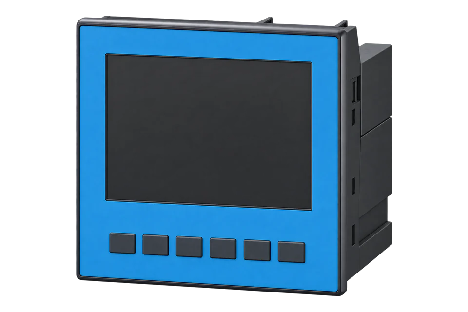
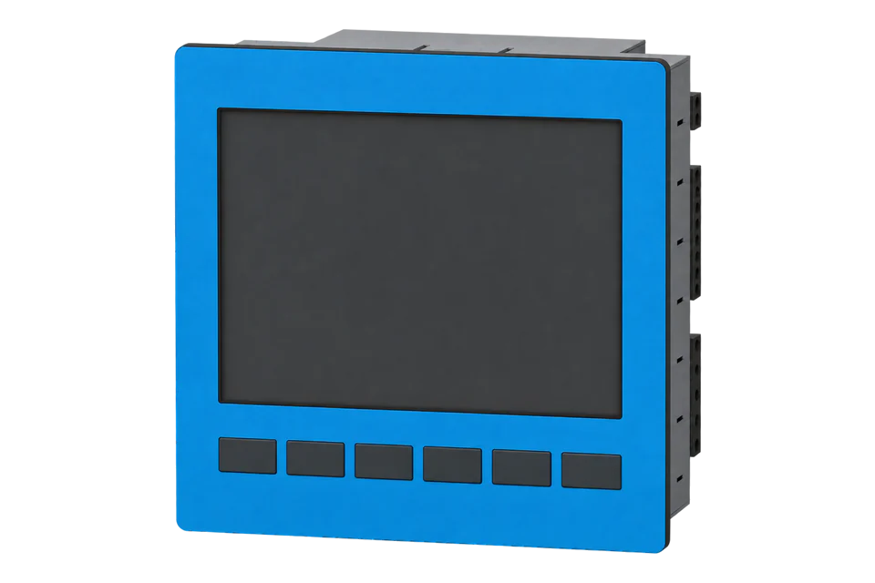
UMG 96-PQ-L combines a front-panel display, external current-transformer inputs and local recording in a 96 × 96 mm instrument. That makes it a different selection from a DIN-rail meter hidden inside a panel: the local display is available for commissioning and routine inspection, while the memory supports a separate historical-data workflow. The base device provides RS-485. Ethernet shown in an expanded system depends on an installed module; it is not a port to assume on every base meter.1
- Installation
- 96 × 96 mm front-panel instrument; indoor or weather-protected cabinet1
- Selected example order references
- 5236001: TN/TT, 230 V supply, standard; 5236021: corresponding Class S version1
- Current inputs
- External ../1 A or ../5 A CTs; separate LP variants are outside this guide1
- Base interface
- RS-485 Modbus RTU; Ethernet requires the appropriate expansion module1
- Memory and I/O
- 64 MB flash; three digital inputs, three digital outputs and one 0–20 mA analogue output1
- Operating temperature
- -10 to +55 °C in the cited manual1
- Selected read
- FC04, literal address 19000, two-register Float in V2
- Byte-order banks
- Printed addresses use big-endian data; add 32768 for the little-endian copy.2
Interface
Documented measurements and integration boundaries for UMG 96-PQ-L.
- Instantaneous phase voltage and current with the configured measurement ratios.
- Signed active power and separately identified energy counters.
- Model-specific power-quality quantities, distinct from archived event records.
- A physical measurement channel and timestamp retained with every collected value.
Assessment
UMG 96-PQ-L base device, using the October 2024 manual for firmware 3.55 and higher and October 2023 map for firmware 3.50 and higher. This procedure targets their overlapping firmware scope, 3.55+. LP sensor-input models and expansion-module endpoints need separate matching documents.
- InteroperabilitySupported with conditions
- The model-specific manual and map define an open serial measurement path; firmware and interface role must match.12
- AccuracySupported with conditions
- The manual defines measurement inputs and capability boundaries. Transformer selection, variant and installation remain part of system accuracy.12
- SecurityNot yet assessed
- No authenticated or encrypted telemetry claim is established for this RS-485 path.12
- ReliabilityNot yet assessed
- Local recording is described, but continuous end-to-end collection and automatic historical backfill are not established.12
- RuggednessSupported with conditions
- The manual states an indoor/cabinet installation and -10 to +55 °C operating range; this is not an outdoor enclosure claim.12
Setup
Read L1-N voltage
The exact model’s address list places L1-N voltage at decimal 19000 as Float in V. The selected instantaneous float includes configured transformer factors.
- Read PDU
- 04 4A 38 00 02: FC04, address 19000, quantity 2.
- Synthetic decoder payload
- 43 66 00 00 decodes as big-endian IEEE754 float32 to 230.0 V.
- Alternate bank
- 19000 + 32768 = 51768 (0xCA38) gives the documented little-endian representation.
- Scaling
- Use the selected Float’s stated engineering unit. Do not apply the configured transformer ratio twice.
Acceptance: These bytes are an independent synthetic decoder example, not a device capture. Verify actual identity, complete response width, selected byte-order bank and agreement with the measurement reference before accepting the reading.
-
Identify the exact instrument
UMG 96-PQ-L base device, using the October 2024 manual for firmware 3.55 and higher and October 2023 map for firmware 3.50 and higher. This procedure targets their overlapping firmware scope, 3.55+. LP sensor-input models and expansion-module endpoints need separate matching documents.
-
Verify the measuring configuration
Check the installed voltage and current transformer ratios, wiring system and phase association. The selected instantaneous Float readings include transformer factors; do not transfer that assumption to every integer energy or alternate-format table.
-
Match the serial role and framing
Read the configured Modbus address, baud rate and serial framing. Confirm that the connection reaches this instrument, not an unintended downstream unit.
-
Read the complete documented quantity
Read FC04 at decimal 19000 (0x4A38), quantity 2, for L1-N voltage. Use the printed big-endian bank with a matching Float32 decoder. These are literal map addresses: do not subtract one.
-
Add current, power and frequency
Add L1 current at 19012 (0x4A44) in A, total active power at 19026 (0x4A52) in W and frequency at 19050 (0x4A6A) in Hz. Read each complete value with FC04, quantity 2, big-endian IEEE-754 Float32, multiplier 1. For example, the current request PDU is 04 4A 44 00 02. These Float readings include the configured transformer factors; do not apply CT/VT ratios again. Compare current and signed power with the display under a known load. Keep the printed bank and decoder together; use the separate +32768 bank only with its little-endian decoder.
Common questions
- Does every UMG 96-PQ-L meet Class S?
- No. The manual lists standard and Class S order references separately. Verify the actual reference and the applicable IEC 61000-4-30 claim; a family name or a successful Modbus read does not establish that classification.1
- Does the base meter have Ethernet?
- The base device’s documented connection is RS-485. The manual shows Ethernet through an expansion module. Check the installed hardware before selecting a TCP collection path.1
- Can I reuse an LP sensor configuration?
- No. Low-power sensor inputs and conventional 1 A/5 A CT inputs are different hardware arrangements. This guide covers the conventional CT-input base meter.1
- Why can a different format need different scaling?
- The map offers several representations. Its general notes distinguish instantaneous Float and short formats, while individual energy tables can add their own ratio and unit rules. Read the definition of the selected entry rather than multiplying every value by the CT ratio.2
Related devices

Sources
- UMG 96-PQ-L user manual and technical data (opens in a new tab) (PDF)
- UMG 96-PQ-L Modbus address list and formulary (opens in a new tab) (PDF)
Further reading
Product names and trademarks belong to their owners. Publication does not imply endorsement or a commercial relationship.