Lovato DMG110
Power and energy meter
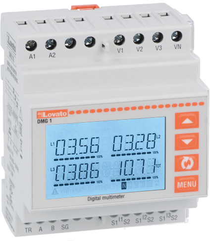
The DMG110 is the RS-485 version of Lovato's four-module DMG100 multimeter. It reads voltage, current, power, power factor, frequency, harmonics and energy from external CTs (/5 A or /1 A) and answers Modbus RTU or ASCII on an isolated serial port. Lovato's DMG protocol document lists it in a column shared with the DMG210, so two details matter: the DMG110 frequency row is scaled in Hz/1000, not the DMG210's Hz/100, and its energy totals are the four-register counters from 1B20H.
Compatibility
Compatible with EpiSensor Edge over Modbus RTU
Lovato documents Modbus RTU on the DMG110's built-in RS-485 port and publishes a register table with addresses, formats and units for read functions 03 and 04. This is documented compatibility, without a physical Edge test.
Lovato DMG110 only, read with the DMG110/DMG210 column of protocol document I317IGB02_22 and manual I422IGB10_17. The DMG100 has no communication port. DMG210 rows that differ (frequency scale, two-register energy, phase sequence) do not apply. Read-only monitoring: no writes to setup or command registers.
Connect it with
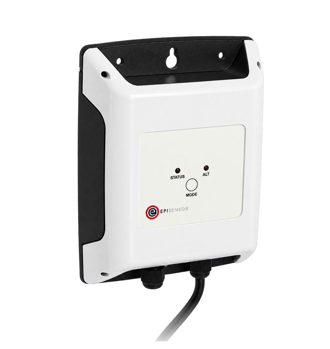
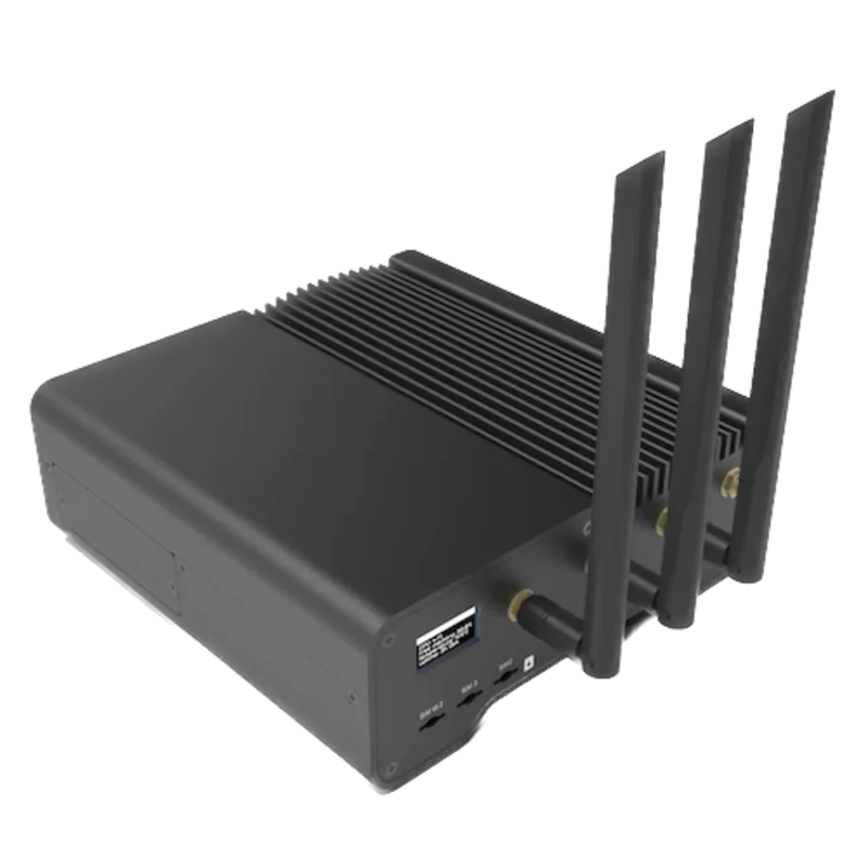
For a DMG110 with its built-in RS-485 port set to Modbus RTU
- Modbus
- Wireless
- Edge
- Platforms
Models
| Models | Interface | Route into Edge |
|---|---|---|
| DMG110 | Built-in isolated RS-485 (TR, A, B, SG); Modbus RTU or ASCII | Read the DMG110/DMG210 column with the DMG110-specific rows described here. |
| DMG100 | Same housing and measurements with no RS-485 terminals | No communication port, so no Modbus read. Check the bottom terminal row for TR, A, B and SG before planning a serial connection. |
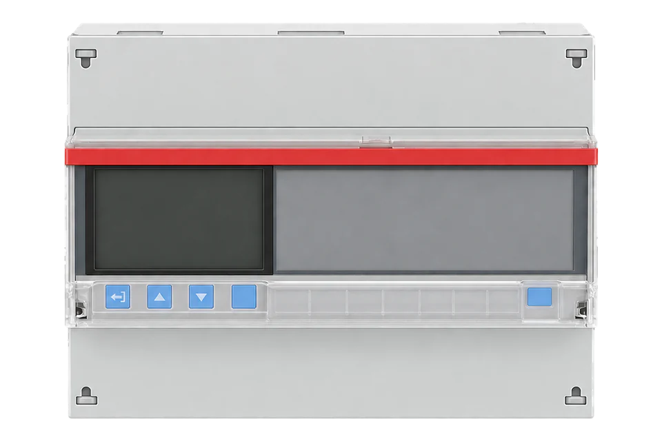
| DMG200 and DMG210 | Graphic-display models; DMG210 has RS-485 and shares the DMG110 table column | A different model. The DMG210 frequency row is Hz/100, its energy totals include two-register counters at 1A20H and its phase sequence is at 2074H. |
| DMG300, DMG600 series, DMG700, DMG800 and DMG900 | Own columns in the same protocol document; some use expansion modules for communication | Use their own column and manual; do not reuse DMG110 scaling or address assumptions. |
Specifications
The DMG110 suits a CT-connected panel or sub-board where a local display is wanted as well as remote readings. It is a three-phase multimeter that also supports single-phase, two-phase and balanced connections; the built-in RS-485 port is what separates it from the DMG100.12
- Current inputs
- External CTs with 5 A or 1 A secondary; CT primary set from 1 to 10000 A. Measuring range 0.025 to 6 A on the 5 A scale.12
- Voltage inputs
- Maximum rated 600 VAC L-L (346 VAC L-N); measuring range 90 to 720 V L-L (50 to 415 V L-N). VT ratios can be set for higher voltages.2
- Auxiliary supply
- 100 to 240 VAC or 110 to 250 VDC; DMG110 consumption 0.8 W, 2.2 VA.2
- RS-485
- Isolated port on terminals TR, A, B and SG. Modbus RTU (default) or ASCII; node address 01 to 255 in menu M07.23
- Serial settings
- 1200 to 115200 bit/s (default 9600); 8 bits with no, odd or even parity, or 7 bits for ASCII; one or two stop bits.2
- Accuracy
- Voltage and current ±0.5% ±0.5 digit within the stated ranges; active energy class 1 (IEC/EN 62053-21), reactive energy class 2 (IEC/EN 62053-23).12
- Housing
- Four DIN modules (DIN 43880) on a 35 mm rail; IP40 on the front, IP20 at the terminals.2
- Environment
- Operating -20 to +60 °C, storage -30 to +80 °C, relative humidity below 80%.2
Interface
Documented measurements and integration boundaries for DMG110.
- Addresses below are the table addresses printed by Lovato. Send each one minus one, with function 03 or 04, at most 64 registers per request.
- Phase voltages L1, L2 and L3 at 0002H, 0004H and 0006H; line voltages at 000EH, 0010H and 0012H: two registers, unsigned 32-bit, V/100.
- Phase currents at 0008H, 000AH and 000CH: two registers, unsigned 32-bit, A/10000.
- Phase active power at 0014H, 0016H and 0018H and equivalent active power at 003AH: two registers, signed 32-bit, W/100. The table switches all power readings to W/10 when the CT and VT ratios allow more than 5 MW per phase.
- Phase power factor at 0026H, 0028H and 002AH and equivalent power factor at 0040H: two registers, signed 32-bit, divide by 10000.
- Frequency at 0032H: two registers, unsigned 32-bit, Hz/1000 on the DMG110. The DMG210 reads the same row in Hz/100.
- Total imported active energy at 1B20H and exported at 1B24H: four registers, unsigned 64-bit, kWh/100. The two-register counters at 1A20H are listed for the DMG210 only.
- Phase sequence at 20F0H (one register, 1 = correct, 0 = not correct) and total hour counter at 1E00H (two registers, unsigned 32-bit, seconds).
Assessment
Lovato DMG110 only, read with the DMG110/DMG210 column of protocol document I317IGB02_22 and manual I422IGB10_17. The DMG100 has no communication port. DMG210 rows that differ (frequency scale, two-register energy, phase sequence) do not apply. Read-only monitoring: no writes to setup or command registers.
- InteroperabilitySupported with conditions
- Lovato documents Modbus RTU on the built-in port, read functions 03 and 04, addresses, formats and units. The table is shared with the DMG210 and some rows carry model or software-revision markers, so each point needs a display check.23
- AccuracySupported with conditions
- Voltage and current ±0.5% and class 1 active energy are stated; system accuracy still depends on the CTs, their ratio setting and correct wiring.12
- SecurityNot yet assessed
- The manual describes passwords for the front-panel menus only. The protocol document also defines write functions 06 and 16 for setup and command registers.23
- ReliabilitySupported with conditions
- The manual gives supply ranges and a 30 ms immunity to supply micro-breaks for the DMG110; the protocol defines exception codes for bad addresses and oversized requests. Treat failed reads as missing data.23
- RuggednessSupported with conditions
- Operating -20 to +60 °C, humidity, shock and vibration figures and IP40 front, IP20 terminals are documented for cabinet mounting.2
- ScalabilitySupported with conditions
- Node addresses 01 to 255, up to 115200 bit/s and 64 registers per request are documented; real bus capacity depends on wiring, repeaters and the poll schedule.23
- LifecycleNot yet assessed
- The product page lists the DMG110 order code with current documentation.1
Setup
First read: frequency with the DMG110 scale
This uses the DMG110/DMG210 column of Lovato protocol document I317IGB02_22 (07/02/2022). Frequency is listed at table address 0032H as an unsigned 32-bit value, Hz/1000 on the DMG110.
- Function
- FC04, read input registers (the table also allows FC03)
- Address
- Table 0032H (50 decimal). Send 0x0031 (49, zero-based). A client with one-based register numbers enters 50.
- Request
- PDU 04 00 31 00 02, two registers. As an RTU frame to node 1: 01 04 00 31 00 02 20 04.
- Decode
- Unsigned 32-bit, high word first as in Lovato's own power example, then divide by 1000 for Hz.
- Example
- Data 00 00 C3 50 = 50000; 50000 ÷ 1000 = 50.000 Hz. Illustrative decode, not a captured meter reply.
- Acceptance
- Matches the frequency page on the display. 5.000 Hz or 500.00 Hz means the wrong scale or model row.
Acceptance: Keep the point when it agrees with the display. If it does not, check the address offset, the node address and that the meter is a DMG110 rather than a DMG210. Record the protocol document revision and the meter's software revision with the configuration.
-
Confirm it is a DMG110
Check the bottom terminal row for TR, A, B and SG next to the CT terminals. A DMG100 has none and cannot be read over Modbus. If your tool supports function 17 (Report slave ID), type 51h identifies a DMG110 and the next byte is its software revision; record it with the configuration.
-
Check CT, VT and wiring settings
Compare menu M01 with the installation: CT primary and secondary (1 or 5 A), VT use and the wiring scheme in P01.07. The installer can run the wiring test (command C.16) on a loaded three-phase circuit to catch phase sequence and CT polarity errors before readings are collected.
-
Match the M07 serial settings
Read the node address, speed, data format and stop bits from menu M07 and enter the same values in Edge. Leave the protocol on Modbus RTU; Modbus ASCII is the other choice. Give every meter on the bus its own address.
-
Wire the RS-485 line
Follow Lovato's RS-485 connection diagram for the A, B, SG and TR terminals and keep the cable a single daisy chain. The manual's diagram groups meters in segments joined by repeaters; plan any long or crowded bus with the installer.
-
Turn on the measurements you need
The manual ships exported energy (P02.09), per-phase energy (P02.10), asymmetry (P02.11) and THD and harmonics (P02.12) switched off. Enable the ones you need and see them on the display before adding their registers to Edge.
-
Start with the frequency read
Read frequency with the example below and compare it with the display. Then add voltages, currents, power and the four-register energy counters, checking each new point against the matching display page.
Common questions
- Why send 0x0031 when the table says 0032H?
- Lovato's protocol document says the address in the request must be one less than the address printed in the table. Its own example reads L2 active power, listed at 0016H, with address bytes 00 15. A client that asks for one-based register numbers takes the table value; one that sends the raw address takes the table value minus one.3
- Can I reuse a DMG210 register list on a DMG110?
- Only with care. The two share a column in Lovato's table, but the frequency row is Hz/1000 on the DMG110 and Hz/100 on the DMG210, the two-register energy counters at 1A20H are marked for the DMG210 only, and phase sequence sits at 20F0H on the DMG110 and 2074H on the DMG210. Use the four-register counters from 1B20H for DMG110 energy.3
- How are the four-register energy counters decoded?
- Each counter at 1B20H and above is an unsigned 64-bit value in kWh/100 (kvarh/100 or kVAh/100 for the reactive and apparent rows). The table marks these rows with a software revision of 07; on earlier software they roll over like the two-register counters, at 19 999 999.99 kWh. Read all four registers in one request, decode most significant word first as in Lovato's two-register example, and check the result against the energy page on the display.3
- Why do exported or per-phase energies not appear?
- The DMG110 manual lists exported energy (P02.09) and per-phase energy (P02.10) as off by default. Turn them on in menu M02 and confirm them on the display before adding those registers.2
Related devices

Sources
- DMG110 product page: order code, description and technical specifications (opens in a new tab)
- Digital multimeter DMG100-DMG110 operating manual I422IGB10_17 (English section) (opens in a new tab) (PDF)
- DMG series Modbus communication protocol I317IGB02_22 (07/02/2022), table 2 and energy tables (opens in a new tab) (PDF)
Further reading
Product names and trademarks belong to their owners. Publication does not imply endorsement or a commercial relationship.