Salus Controls FC600
Fan coil thermostat
A mains-powered Zigbee thermostat for 2-pipe and 4-pipe fan coil units. It switches two 230 V AC valve outputs and a three-speed fan, rated 5(2) A, from its own room sensor or an external NTC probe.
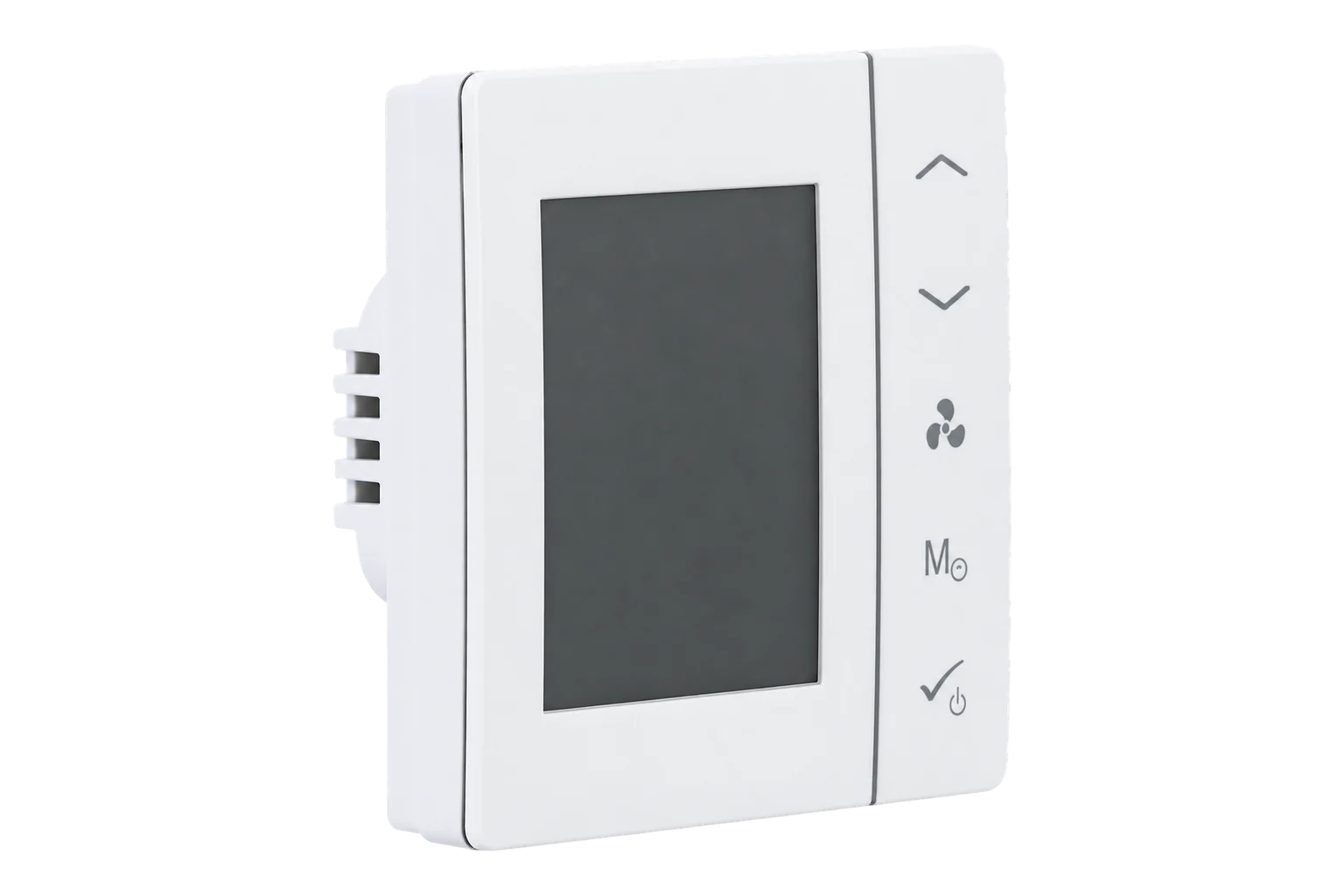
- Zigbee
Fan coil thermostat
Compatibility
Compatible with EpiSensor Edge over Zigbee.
Pair it with the Zigbee radio on an EpiSensor Gateway. Edge reads it locally on the Gateway.
Edge reads 10 values from it, listed under Interface.
Connect it with
-
Gateway ZGW-20From €899 ex VAT Configure Gateway

Specifications
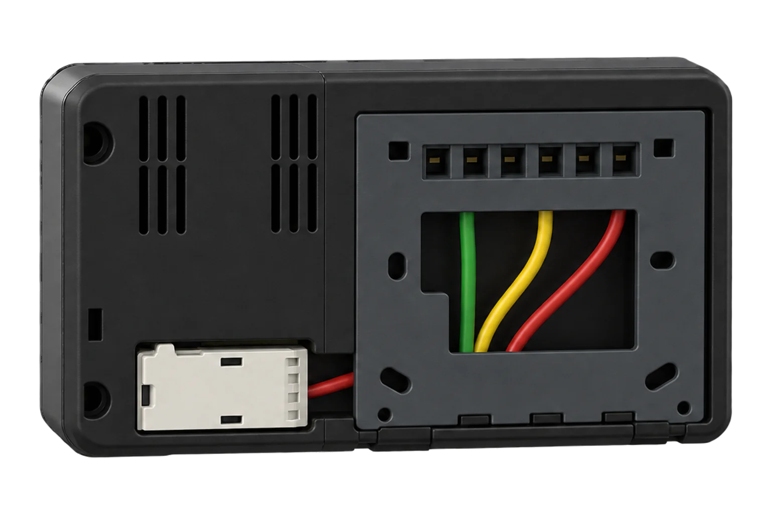
It measures room temperature every 15 seconds over 0 to 45 °C. Two inputs, S1 and S2, change what it does. S1 takes a heat/cool changeover switch or a 10 kΩ NTC pipe sensor. S2 takes an occupancy contact, such as a hotel key card switch that sends the room to ECO or standby, or an external 10 kΩ NTC room sensor that replaces the internal one. Control is TPI or span, and it keeps frost protection at 5 °C even in standby.1
- Power
- Mains. 230 V AC +10 % −15 %, 50 Hz on terminals L and N. The same supply feeds the 230 V AC valve and fan outputs, and user settings survive a power cut.1
- Outputs
- V1 and V2 valves, F1 to F3 fan speeds, all 230 V AC1
- Output rating
- 5(2) A2
- Systems
- 2-pipe or 4-pipe fan coils1
- Setpoint range
- 5 to 40 °C1
- Measuring range
- 0 to 45 °C1
- Display resolution
- 0.5 °C or 0.1 °C, selectable1
- Temperature offset
- −3.0 to +3.0 °C in 0.5 °C steps1
- Temperature sampling
- Every 15 seconds1
- Sensor inputs
- S1 and S2, NTC 10 kΩ, B25/50 = 3950 K1
- Control algorithm
- TPI or span, set by parameter d151
- Frost protection
- 5 °C, always on1
- Operating conditions
- 0 to 50 °C, below 95 % RH non-condensing1
- Ingress protection
- IP30, indoor use only1
- Mounting
- Flush, in a 60 mm wall box1
- Dimensions
- 86 × 86 × 42 mm2
- Wireless
- Zigbee, 2.4 GHz2
Where it is used
Fan coil schedules checked against HVAC energy: the running state shows when each room calls for heating or cooling, beside the metered supply to the fan coils and plant.
HVAC energy monitoring for commercial buildingsHotel rooms, with a key card switch on S2 sending an empty room to ECO or standby and Edge setting the occupied setpoint and fan mode.
Room temperature and heating or cooling demand logged per zone, to check comfort against the schedule the building is meant to run.
Indoor environmental monitoring
Interface
Readings and settings, with units and ranges where Salus Controls publishes them. readable, readable and writable.
| Reading | Unit | Range or values | Access |
|---|---|---|---|
| Measurements 4 | |||
| Climate | - | - | Read only |
| Local temperature | °C | - | Read only |
| Running mode | - | offcoolheat |
Read only |
| Running state | - | idleheatcool |
Read only |
| Controls 4 | |||
| Occupied heating setpoint | °C | 5 to 40 °C | Read and write |
| System mode | - | offheatcoolauto |
Read and write |
| Fan mode | - | offlowmediumhighauto |
Read and write |
| Preset | - | scheduletemporary_overridepermanent_overridestandbyeco |
Read and write |
| Settings 2 | |||
| Local temperature calibration | °C | -3 to 3 °C | Read and write |
| Keypad lockout | - | unlocklock1lock2 |
Read and write |
The thermostat answers on endpoint 9. Zigbee2MQTT’s converter configures it to report room temperature, heating setpoint, system mode, fan mode, running mode and running state.4
There is one writable setpoint, occupied_heating_setpoint, from 5 to 40 °C in 0.5 °C steps. The converter does not expose a separate cooling setpoint.4
The preset maps to the thermostat’s own hold types: schedule, temporary override, permanent override, standby and eco.14
Installer parameters d00 to d34 are set on the thermostat with code 49, and only while it is not connected to a gateway. Set the pipe configuration, the S1 and S2 inputs and the ECO setpoints before pairing.1
Setup
-
Configure it locally first
Wire and power the thermostat, then choose 2-pipe or 4-pipe and the S1 and S2 functions. Other installer parameters are reached with code 49. The installer menu is not available once the thermostat is connected to a gateway.1
-
Open pairing in Edge
In Edge, open pairing on the Gateway’s Zigbee network so the Gateway accepts new devices.
-
Join from a new thermostat
On first power-up the display shows UG YES. Press OK, then press OK again when it shows PAIR. The antenna icon appears in the corner of the display while it joins.1
-
Or join one already in use
Hold the fan, M and OK buttons for 3 seconds, enter code 55 with the arrow buttons and press OK. Select UG YES, press OK, then confirm PAIR.1
-
Check a reading and a control
Check that Edge identifies it as Salus Controls FC600 and that the room temperature matches the display. Change the setpoint from Edge and confirm the display follows it.
Common questions
- Does the FC600 need a Salus gateway to work with Edge?
- No. Salus uses its UG600 or UGE600 gateway for the Salus Smart Home app, but the FC600 is a Zigbee device with a Zigbee2MQTT converter, so it joins the Zigbee radio on an EpiSensor Gateway directly. It then sits on that network instead of a Salus gateway.14
- Does it work with 2-pipe and 4-pipe fan coils?
- Yes. In a 2-pipe system V1 switches the heating or cooling valve and V2 is not used. In a 4-pipe system V1 switches the heating valve and V2 the cooling valve. Parameter d01 selects which.13
- Can the installer settings be changed over Zigbee?
- No. Pipe configuration, the S1 and S2 inputs, TPI or span control, the ECO setpoints and the other installer parameters are set on the thermostat in installer mode, which works only while it is not connected to a gateway.14
- What load can the outputs switch?
- The valve and fan outputs are 230 V AC and Salus rates them at 5(2) A. The thermostat is supplied at 230 V AC +10 % −15 %, 50 Hz.12
- Can it use a remote temperature sensor?
- Yes. A 10 kΩ NTC sensor on S2 replaces the internal sensor, which suits a thermostat mounted away from the room or a return-air measurement. In a 2-pipe system a pipe sensor on S1 can also switch heating and cooling automatically, at 30 °C and 10 °C by default.1
Related devices
More from Salus Controls
Sources
- Fan Coil Thermostat FC600 instructions manual (V014, April 2019) (opens in a new tab) (PDF)
- FC600 Fan Coil Thermostat (opens in a new tab)
- FC600 Fan Coil Thermostat quick guide (opens in a new tab) (PDF)
- Salus Controls FC600 converter (salus_controls.ts) (opens in a new tab)
- Salus Controls FC600 device documentation (opens in a new tab)
Further reading
Product names and trademarks belong to their owners. Publication does not imply endorsement or a commercial relationship.