ComAp InteliMains NT
Mains supervision controller
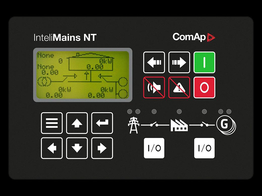
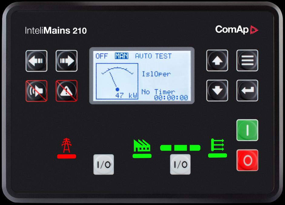
InteliMains NT with order code IM-NTGC is a mains supervision and switchgear controller with its own display. It coordinates groups divided by bus-tie breakers. This guide covers the GC unit in the cited datasheet, rather than treating NT BaseBox or NTC BaseBox products as interchangeable.
- Modbus RTU
Mains supervision controller
Compatibility
Documented Modbus RTU interface
Documented RS-232 Modbus slave; use an isolated RS-232 to RS-485 converter for the Edge serial monitoring route.
The 2019 datasheet documents RS-232 Modbus slave communication for IM-NTGC. RS-232 is not RS-485, and the controller is not a native Ethernet endpoint. CAN2 links used for group supervision serve a separate purpose.
Connect it with
-
Modbus Interface ZMB-3XFrom €399 ex VAT Configure Modbus Interface
-
Gateway ZGW-20From €899 ex VAT Configure Gateway


When the documented monitoring interface is fitted and configured
- Modbus
- Edge
- Platforms
Models
| Models | Interface | Route into Edge |
|---|---|---|
| InteliMains NT | Documented Modbus slave over RS-232; use an appropriate serial-network intermediary for Edge | Save the GenConfig application and its Modbus value list. Use the documented RS-232 slave interface through a serial intermediary with a matching RTU port; record its Ethernet-side protocol and unit mapping before configuring Edge. |
Specifications
The 2019 datasheet documents RS-232 Modbus slave communication for IM-NTGC. RS-232 is not RS-485, and the controller is not a native Ethernet endpoint. CAN2 links used for group supervision serve a separate purpose.12
Interface
Documented measurements and integration boundaries for InteliMains NT.
- Mains and switchgear electrical measurements in the application value list
- Bus-tie and mains breaker indications
- Controller alarms and supervised group states
Assessment
Documented Modbus slave over RS-232; use an appropriate serial-network intermediary for Edge
- InteroperabilitySupported with conditions
- Documented Modbus slave over RS-232; use an appropriate serial-network intermediary for Edge12
- AccuracySupported with conditions
- The documentation identifies electrical and operating measurements for this plant role. CT configuration and measurement location determine how those values are used.12
- SecurityNot yet assessed
- The cited documentation does not establish an authenticated, encrypted Edge monitoring connection.
- ReliabilityNot yet assessed
- The controller application distinguishes operating conditions and alarms. Retain communication availability alongside the plant readings.
- RuggednessNot yet assessed
- Installation and enclosure requirements depend on the panel and the exact hardware variant.
- ScalabilityNot yet assessed
- Assign one device identity per controller and keep generator, mains and busbar measurements separate.
Setup
-
Save the GenConfig application and its Modbus value list.
Use the documented RS-232 slave interface through a serial intermediary with a matching RTU port; record its Ethernet-side protocol and unit mapping before configuring Edge.
-
Record CT ratios and the physical measurement location.
Compare the first electrical values with the controller display before using them in totals or trends.
-
Keep missing responses distinct from a stopped generator.
Store communication availability beside running state so a disconnected cable does not look like healthy standby.
-
Build a read-only point list for monitoring.
Remote start, synchronisation and breaker operation require a separate control design with the existing panel interlocks and feedback.
Related devices
Sources
Further reading
Product names and trademarks belong to their owners. Publication does not imply endorsement or a commercial relationship.