ABB M1M 20 Modbus
Power and energy meter
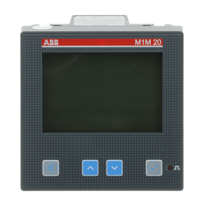
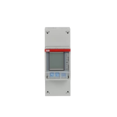
M1M 20 Modbus, order code 2TAZ662012R2000, measures single- or three-phase circuits through conventional 1 A or 5 A CTs. Its isolated serial interface connects to Edge for voltage, current, power and power-factor monitoring. Select this exact communications version before applying the M1M map.
Compatibility
Compatible with EpiSensor Edge over Modbus RTU
ABB publishes the serial interface, FC03 reads and model-specific register widths and resolutions.
M1M 20 Modbus with conventional CT inputs. Start with the M1M20 applicability column in protocol 1.3 and user manual revision C. At commissioning, confirm the installed order code, firmware, marked accuracy class, CT ratio and wiring, then compare the first reading with the display.
Connect it with
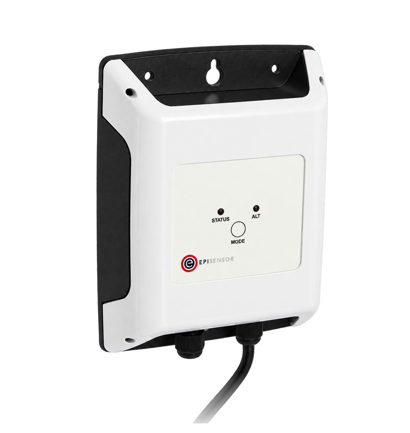
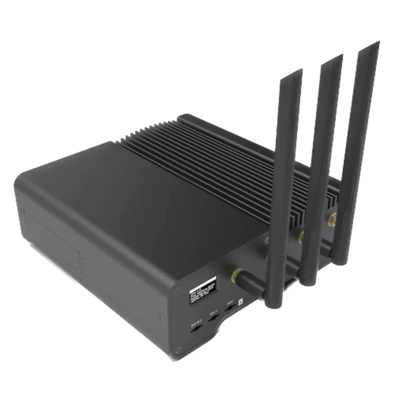
For the M1M 20 Modbus serial version
- Modbus
- Edge
- Platforms
Models
| Models | Interface | Route into Edge |
|---|---|---|
| M1M 20 Modbus · 2TAZ662012R2000 | Isolated RS-485 and conventional 1 A/5 A CT inputs; no digital I/O on this version. | Use its serial port for local measurement reads. |
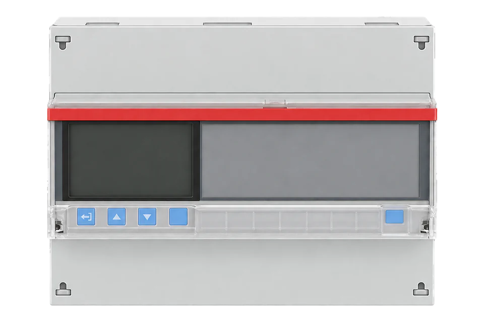
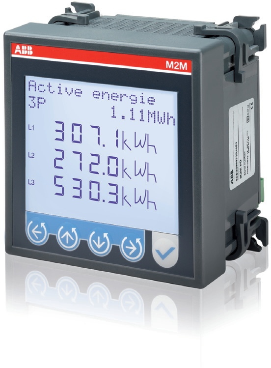
| M1M 20 / Ethernet / I/O / I/O Pro | Separate versions provide no communications, Ethernet or additional I/O. | Identify the label and terminals; a similar front panel does not establish the installed interface. |
Specifications
The conventional-CT serial model suits electrical panel monitoring. Its M1M protocol is a separate source from the M4M family map. Choose complete supported quantities and reject unavailable raw markers before scaling.12
- Exact version
- M1M 20 Modbus · 2TAZ662012R20003
- Measurement inputs
- 1 A or 5 A CT secondary; 50 mA–6 A input range. Voltage range 80–265 VAC L-N.1
- Accuracy in current manual
- Revision C states active-energy class 0.5 to IEC 61557-12 and class 0.5S to IEC 62053-22; voltage/current class 0.5. CT and installation errors remain additional.1
- Auxiliary supply
- 100–230 V AC/DC ±15%, maximum 5 VA.1
- Serial settings
- Address 1–247; 9600, 19200, 38400, 57600 or 115200 bit/s; odd/even parity with one stop bit, or no parity with one/two stop bits.1
- Panel environment
- 96 × 96 × 85 mm; front IP51, terminals IP20; operating −5 to +55 °C; humidity up to 95% without condensation.1
Interface
Documented measurements and integration boundaries for M1M 20 Modbus.
- L1 voltage at 0x5B02: two unsigned registers, 0.1 V resolution. L1 current at 0x5B10: two unsigned registers, 0.01 A resolution.
- Total active power at 0x5B1A: two signed registers, 0.01 W resolution. Total power factor at 0x5B40: one signed register, 0.001 resolution.
- Import/export active energy at 0x5000/0x5004 occupies four registers per value. Edge’s Modbus client does not read these 64-bit counters. Use the meter display for those totals; do not decode a partial counter.
Assessment
M1M 20 Modbus with conventional CT inputs and its documented serial interface.
- InteroperabilityWell supported
- A published Modbus RTU map gives FC03, addressing, types and model applicability for a standard serial connection.2
- AccuracySupported with conditions
- CT ratios, wiring mode and the documented accuracy conditions define the measurement. Complete 32-bit electrical readings are usable; four-register energy totals exceed Edge’s Modbus read width.12
- SecurityLimited
- The configuration menu has a password and ABB requires network safeguards. Plain serial Modbus does not authenticate or encrypt the read path; restrict physical and network access and keep monitoring read-only.12
- ReliabilitySupported with conditions
- The manual defines a ±15% auxiliary-supply tolerance and names IEC 61326-1 EMC and IEC 61010-1 safety requirements. Keep the supply and panel environment within the documented limits.1
- RuggednessSupported with conditions
- IP51 applies to the front and IP20 to the terminals. The −5 to +55 °C, non-condensing envelope calls for a suitable panel enclosure.1
Setup
Read L1 phase voltage
Protocol 1.3 defines FC03, big-endian data and the M1M20 L1-voltage row on page 12.
- Function
- FC03 Read Holding Registers
- PDU address and length
- 0x5B02 = 23298; 2 registers
- Request PDU
- 03 5B 02 00 02
- Synthetic response data
- 00 00 08 FC → unsigned 2300 × 0.1 V = 230.0 V
- Acceptance
- Compare with L1-N on the meter display in a wiring mode that provides phase voltage.
Acceptance: The 230.0 V value is a calculated example, not a device capture. The RTU client supplies the configured slave address and CRC. Retain only read operations in the monitoring poll.
-
Confirm CT and wiring settings
Have the authorised installer verify the wiring mode, CT primary/secondary ratio and any voltage transformer ratio. L1-N voltage is not available in every wiring system.
-
Copy the actual communications settings
Read CONF / COMM / ADDR, BAUD and BYTE from the meter. Match them in Edge. Do not change meter configuration or reset energy totals as part of this read check.
-
Read one complete value
Use FC03 with start address 0x5B02, decimal 23298, and quantity 2. The M1M example sends the hexadecimal table address directly; do not subtract one or add a 40001 reference prefix.
-
Compare before extending the point list
Decode an unsigned 32-bit value, high word first, then multiply by 0.1 V. Reject FFFF unavailable markers before scaling. Compare with the simultaneous L1-N display, then add current and signed power using their own widths and scales.
Common questions
- Can I use an M4M template because the addresses look similar?
- Use the M1M source and its product-applicability column. Similar addresses do not establish identical hardware, functions or firmware scope.2
- Why is voltage unavailable?
- ABB uses FFFF for data the configured device cannot measure or calculate. A three-phase three-wire system does not supply phase-to-neutral voltage. Treat unavailable as missing, not zero.2
- Does this serial version provide Ethernet or I/O?
- No. The user manual separates the Modbus, Ethernet, I/O and I/O Pro versions. Select the actual version before planning its connection or signals.1
Related devices


Sources
- M1M 20 user manual, 2CSG445081D0201 revision C (opens in a new tab)
- M1M Modbus manual, 9AKK108467A2704 version 1.3 (opens in a new tab)
- M1M 20 Modbus official product record, 2TAZ662012R2000 (opens in a new tab)
Further reading
Product names and trademarks belong to their owners. Publication does not imply endorsement or a commercial relationship.