Victron Energy Cerbo GX MK2
Battery and energy-system communications hub
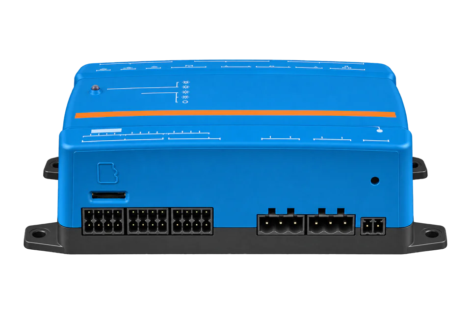
Cerbo GX MK2 brings connected Victron equipment into one local energy-system interface. It is a communications hub, not a power inverter or a calibrated energy meter. A Modbus TCP client selects the system aggregate or an individual connected service using the unit ID, then reads the registers belonging to that service. The available measurements therefore depend on the equipment actually connected.
- Modbus TCP
Battery and energy-system communications hub
Compatibility
Compatible through local Modbus TCP
Victron documents a local Modbus TCP gateway for GX devices. Edge reads its published register map using the unit ID of the required connected service.
Cerbo GX MK2 part numbers BPP900450110 and BPP900451100. The current manual also covers MK3; its higher VE.Direct device limit is not a MK2 specification. This guide reads data only and does not configure ESS control, battery limits or generator operation.
Connect it with
-
Gateway ZGW-20From €899 ex VAT Configure Gateway
-
Evaluation Gateway on a Raspberry Pi Edge with one device licensedFree Set up Evaluation Gateway on a Raspberry Pi

For local measurements from equipment already visible on the GX device
- Modbus
- Edge
- Platforms
Models
| Models | Interface | Route into Edge |
|---|---|---|
| Cerbo GX MK2, BPP900450110 / BPP900451100 | 8–70 V DC communications hub; Ethernet, VE.Bus, VE.Direct and VE.Can interfaces | Read the configured local Modbus gateway and preserve the service-to-unit-ID mapping. |
| Cerbo GX MK3, BPP900451130 | Separate hardware revision; the current manual lists up to 25 VE.Direct devices versus 15 for MK2 | Do not apply MK3 capacity to a MK2 installation. |
| Original Cerbo GX and Cerbo-S GX | Earlier hardware with separate archived manuals | Many functions depend on Venus OS, but hardware ports and limits must come from the exact model manual. |
Specifications
MK2 is a low-voltage DC-powered hub for connected energy equipment. Its three physical VE.Direct ports can be extended through USB within the documented 15-device total, which includes both direct and USB-connected VE.Direct devices. The measured accuracy belongs to the connected meter, monitor or inverter rather than the hub.12
- Exact hardware
- Cerbo GX MK2: BPP900450110 or BPP9004511002
- Supply
- 8–70 V DC2
- Network
- 10/100 Ethernet; Wi-Fi available2
- VE.Direct capacity
- 3 physical ports; maximum 15 connected VE.Direct devices in total, including USB2
- System unit ID
- 100 for com.victronenergy.system; connected services use their listed IDs1
- Installation envelope
- IP20; -20 to +50 °C; wall mounting or optional DIN-rail adapter2
Interface
Documented measurements and integration boundaries for Cerbo GX MK2.
- System aggregate data from com.victronenergy.system, using unit ID 100.
- Battery monitor, SmartShunt or supported CAN-battery measurements through the corresponding battery service.
- VE.Bus inverter/charger AC input and output data, selected by the actual service unit ID.
- Solar-charger data from connected VE.Direct or VE.Can equipment.
- Grid-meter and PV-inverter data only when those devices are present and correctly configured on GX.
- Last Modbus error and device availability to distinguish a missing service from a legitimate zero reading.
Assessment
Cerbo GX MK2 hardware BPP900450110/BPP900451100; read-only Modbus gateway integration with connected equipment.
- InteroperabilityWell supported
- The public GX protocol documents function codes, per-service unit IDs, the register workbook and a worked read. Available points depend on the connected service.1
- AccuracySupported with conditions
- System and individual-device services are distinguished. The hub does not supply a measurement-accuracy class; suitability depends on the connected monitor, meter or inverter and its configured role.12
- SecuritySupported with conditions
- Venus OS documents network security profiles and authenticated console access. Modbus remains a separately enabled read/write service requiring local access restriction.14
- ReliabilitySupported with conditions
- The 8–70 V DC power range, named EMC/safety standards, persistent unit IDs and stored firmware backup provide documented operating and recovery boundaries. Connected-device failure still produces unavailable readings.125
- RuggednessSupported with conditions
- IP20 and -20 to +50 °C suit a protected cabinet or indoor installation. An outdoor or wet site needs an appropriate enclosure rather than relying on the hub housing.2
Setup
Read VE.Bus voltage and system battery measurements
Victron’s GX manual provides this example for a Multi or Quattro connected over VE.Bus. It tests service selection and scaling, not the Cerbo’s own supply voltage.
- Target
- Unit ID 246 in the manufacturer example; use the actual VE.Bus ID shown under Available services
- Function
- FC03 Read Holding Registers; Victron also supports equivalent FC04 reads
- Address and length
- PDU address 3, one register; do not subtract one
- Request PDU
- 03 00 03 00 01
- Manufacturer example
- Raw register 2302, hexadecimal 0x08FE
- Independent response/decode fixture
- 03 02 08 FE gives U16 2302; divide by 10 = 230.2 V AC
- Acceptance boundary
- A connected VE.Bus service and valid AC input are required. Check the same quantity and phase on the GX screen.
- System battery block
- For system battery totals, use unit 100, FC03 wire 840, quantity 4: PDU 03 03 48 00 04. Registers 840/841/842/843 are voltage U16 ÷10 V, current S16 ÷10 A, power S16 W and SOC U16 %. These belong to com.victronenergy.system, not the individual battery-service map.
- Synthetic battery decode
- Data 02 08 FF 83 FD 76 00 4C gives 52.0 V, -12.5 A, -650 W and 76%. The workbook defines positive current/power as charging and negative as discharging. Compare the selected system battery source on GX; system SOC uses scale 1, not the individual battery-service scale 10.
Acceptance: Use the published workbook as a best-effort point map and compare fresh values with the same GX service or system view. The original VE.Bus read and new battery block have different measurement sources. These synthetic examples establish decoding, not physical-site qualification.
-
Confirm MK2 and the measurement source
Record the GX part number and Venus OS version. Check that the target inverter/charger, battery monitor or meter already appears correctly in the GX device list. A gateway cannot expose measurements from equipment that is absent or not communicating.
-
Enable the GX Modbus service
Enable Modbus TCP in the GX settings. The GX Modbus manual documents Settings, Services, Modbus/TCP; menu placement can differ with Venus OS interface versions. Use the service’s Available services list to record unit IDs. Keep the IP endpoint on a protected local network.
-
Choose system totals or an individual service
Use unit ID 100 for com.victronenergy.system registers. For VE.Bus, battery, grid-meter or solar-charger registers, use the service ID listed on GX. Keep the service name with each point: a numerical unit ID alone does not define the register map. The published workbook provides the point types and scaling.
-
Perform the bounded voltage read
For a connected VE.Bus Multi or Quattro, verify its unit ID and read register address 3 as shown below. Compare the decoded AC input voltage with the corresponding GX device screen. Do not compare it with an unrelated phase, AC output or DC battery voltage.
-
Handle absent data and changes
Read only defined registers and do not combine blocks across unsupported gaps. Treat missing-device and illegal-address exceptions as unavailable data. Reconfirm the service mapping and available measurements after adding equipment, replacing hardware or updating Venus OS; the manufacturer documents unit IDs as persistent across reboot.
Common questions
- Why does unit ID 100 not return my battery-monitor registers?
- Unit ID 100 selects the aggregate system service. Individual battery services have separate IDs and register sets. The same IP address can expose many logical devices, so both fields must match.1
- Can I read every register in one large block?
- Only combine contiguous registers that exist for that service. Victron warns that a request spanning nonexistent registers fails. Available data also varies between battery monitors and CAN-connected batteries.1
- Does the GX security profile encrypt Modbus TCP?
- The network security profile governs services such as Remote Console access. The documented Modbus TCP path is separate; do not assume an HTTPS login protects its register traffic. Restrict Modbus access on the local network and keep control commands out of the monitoring client.14
Related devices
More from Victron Energy
Sources
- GX Modbus-TCP manual: unit IDs, registers and worked voltage example (opens in a new tab)
- Cerbo GX manual: MK2 and MK3 technical specifications (opens in a new tab)
- Cerbo GX manual: product role and discontinued-model documentation (opens in a new tab)
- Cerbo GX manual: user interface and network security profiles (opens in a new tab)
- Cerbo GX manual: firmware updates and stored firmware backup (opens in a new tab)
- GX Modbus TCP register list 3.81, revision 54 (opens in a new tab)
Further reading
Product names and trademarks belong to their owners. Publication does not imply endorsement or a commercial relationship.