Victron Energy Lynx Smart BMS NG
Battery management system
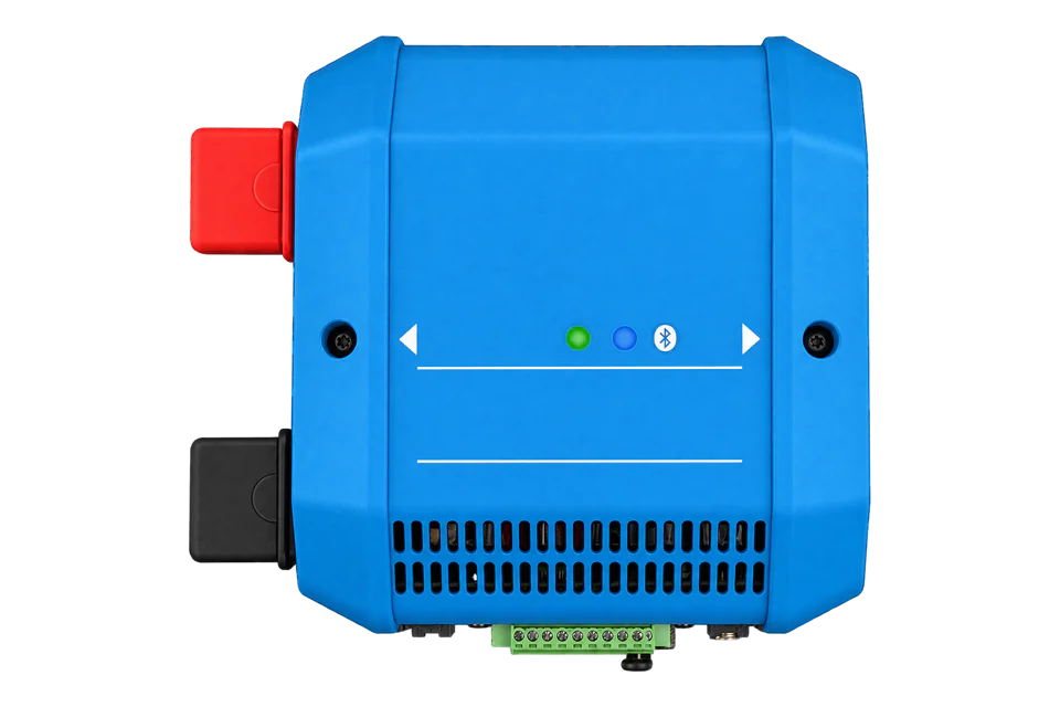
A BMS, shunt and safety contactor for Victron Lithium NG batteries. Compare the 500 A and 1000 A M10 versions, and read battery data through a compatible GX device without bypassing charge or discharge protection.
- VE.Can
- Bluetooth
Battery management system
Compatibility
Monitoring through a GX device only
Victron documents Lynx Smart BMS NG measurements over VE.Can to a GX device. A GX device exposes supported battery-service measurements through its separately enabled Modbus TCP service. Confirm the actual service and available fields on the installed system.
Lynx Smart BMS NG 500A (M10) and 1000A (M10), for Victron Lithium NG batteries. The older non-NG Lynx Smart BMS and Lithium Battery Smart family are not interchangeable with this NG battery connection. Edge monitoring is read only; ATC/ATD, DVCC and the safety contactor remain under the battery system’s control.
A commissioned Lynx NG bank is already visible on a compatible GX device
- Wired
- Edge
- Platforms
Models
| Models | Interface | Route into Edge |
|---|---|---|
| Lynx Smart BMS NG 500A (M10) | 500 A continuous contactor; 600 A for 5 minutes; 190 × 180 × 80 mm; 1.9 kg | VE.Can to GX; the same monitoring approach as the 1000A version. |
| Lynx Smart BMS NG 1000A (M10) | 1000 A continuous contactor; 1200 A for 5 minutes; 230 × 180 × 100 mm; 2.7 kg | A higher contactor rating does not raise the battery, fuse, cable or inverter rating. |
| Lithium NG versus Lithium Battery Smart | NG battery BMS cables use circular three-pole connectors with an M8 screw ring | Match the bank to the NG BMS. The legacy battery family needs its appropriate BMS; similar product names are not an interchangeability guarantee. |
Specifications
The contactor current rating is one component limit, not the permitted current of every connected bank. Battery limits, fusing, busbars, conductors and inverter/charger ratings still govern the installed system. These BMS units have no energy-storage capacity of their own.1
- Supported system voltage
- 12, 24 or 48 V systems; BMS supply range 9–60 V DC1
- 500A variant
- 500 A continuous; 600 A for 5 minutes; approximately 2.6 W in ON mode at 12 V1
- 1000A variant
- 1000 A continuous; 1200 A for 5 minutes; approximately 4.2 W in ON mode at 12 V1
- Communications
- VE.Can to GX; Bluetooth for VictronConnect; RJ10 to Lynx Distributors1
- Battery connection
- Victron Lithium NG only; up to 50 batteries subject to the battery-system design rules1
- Environmental limits
- IP22; -40 to +60 °C; maximum 95% relative humidity, non-condensing1
- Protection architecture
- ATC/ATD contacts and GX DVCC are primary controls; contactor provides secondary protection1
- Auxiliary output
- 1.1 A continuous; can keep GX powered temporarily after a low-cell-voltage shutdown, not indefinitely1
Interface
Documented measurements and integration boundaries for Lynx Smart BMS NG.
- Battery state of charge, voltage and current from the BMS monitoring function, where exposed by the actual GX battery service.
- Cell voltages, temperatures and alarms displayed by GX over VE.Can; inspect the GX Modbus workbook before assuming those details are externally readable.
- Operational state and pre-alarm information in the Victron system; data loss is not a command to bypass the safety controls.
- Lynx Distributor fuse status through supported connected distributors; the manual requires distributor serial HQ1909 or later for fuse-status communication.
Assessment
Lynx Smart BMS NG 500A (M10) and 1000A (M10), for Victron Lithium NG batteries. The older non-NG Lynx Smart BMS and Lithium Battery Smart family are not interchangeable with this NG battery connection. Edge monitoring is read only; ATC/ATD, DVCC and the safety contactor remain under the battery system’s control.
- InteroperabilitySupported with conditions
- VE.Can to GX and the separate GX Modbus service provide a documented mediated path. Available fields depend on the actual GX battery service, not a direct Lynx TCP endpoint.13
- AccuracySupported with conditions
- The integrated shunt and monitor report current and state of charge. The reviewed manual does not establish a revenue-energy accuracy class; these readings support battery operation and monitoring.1
- SecuritySupported with conditions
- Bluetooth can be disabled and re-enabled from GX. The Modbus endpoint is on GX and requires network restriction; the documented monitoring path does not add encrypted Modbus.13
- ReliabilitySupported with conditions
- The manual separates primary ATC/ATD/DVCC protection from the fallback contactor and documents pre-charge, alarms and AUX-supply shutdown behavior. Monitoring must preserve those controls.1
- RuggednessSupported with conditions
- IP22 requires a protected location. The published -40 to +60 °C range is for the BMS and does not override the batteries’ separate charging and operating limits.1
- ScalabilitySupported with conditions
- The manual supports up to 50 NG batteries per BMS under its design rules and up to five paralleled BMS units with matching current ratings and separate banks.1
Setup
Read the Lynx battery service through GX
The GX register workbook provides these read-only battery-service points. Use them as best-effort starting points after the NG BMS appears correctly on GX. Edge connects to GX Modbus TCP; the Lynx VE.Can link is the upstream battery connection.
- Select the service
- Use the GX IP and configured Modbus TCP endpoint, with the Lynx com.victronenergy.battery unit ID shown in Available services. Venus OS assigns service IDs dynamically from version 2.60; do not copy a historical preferred ID. An individual BMS and a parallel virtual BMS represent different battery boundaries.
- Voltage request
- FC03 wire 259, quantity 1: PDU 03 01 03 00 01. Battery voltage is U16 ÷100 V. Synthetic data 14 50 gives raw 5200 ÷100 = 52.00 V. Addresses are already PDU addresses; do not subtract one. FC04 provides equivalent reads on GX.
- Current and SOC
- Read wire 261 and wire 266 separately, quantity 1 each. Current is S16 ÷10 A: synthetic FF 83 gives -12.5 A, discharging under the published convention. SOC is U16 ÷10 %: 02 F3 gives 75.5%. System unit 100 SOC at 843 instead uses whole percent; do not swap these maps.
- Availability and comparison
- Compare the same battery service and timestamp on GX. Read defined points without crossing unsupported gaps. A missing service or illegal-address exception is unavailable data, not an empty battery. Keep the GX intermediary, VE.Can termination and existing battery controls in place.
Acceptance: This is a document-based read example through GX, not a direct Lynx Ethernet endpoint or a physical Edge qualification. ATC/ATD, DVCC and the safety contactor remain under the battery system’s control.
-
Identify the NG battery system
Check that the battery bank is Victron Lithium NG and the BMS is the 500A or 1000A NG M10 version. Size the complete system with the manufacturer installation rules. Do not infer safe cable, fuse or battery current from the contactor rating alone.
-
Preserve the protection design
Have the installer commission ATC/ATD and the appropriate GX DVCC controls. The contactor is a fallback, not a substitute for orderly charger/load control. External monitoring must not bypass a low-cell-voltage, temperature or charge-limit condition.
-
Verify the GX connection
Use the documented VE.Can connection and termination and confirm that the correct BMS, bank measurements and alarms appear on GX. The AUX supply can keep GX alive briefly after load shutdown; a later loss of telemetry must remain visible as unavailable data.
-
Select the battery service
Enable the GX Modbus TCP service on a restricted local network. Record the installed Venus OS version and battery service unit ID from Available services. Unit ID 100 is the system aggregate, not automatically the individual Lynx battery service. Read the current official register workbook for that service.
-
Check monitoring against GX
On the selected battery service, start with voltage 259 (U16 ÷100 V), current 261 (S16 ÷10 A) and SOC 266 (U16 ÷10 %). Compare the same battery and timestamp on GX. The documented current convention is positive charging, negative discharging. Keep missing-service errors visible and leave charge/discharge limits and relay control unchanged.
Common questions
- Can I connect the VE.Can RJ45 port to an Ethernet switch?
- No. The connector shape does not make VE.Can Ethernet. Connect it through the documented VE.Can path to GX; use the GX network interface for Modbus TCP monitoring.13
- Does the 1000A model store more energy?
- The BMS stores no usable battery energy. Its higher current rating supports a different system design. Capacity comes from the approved battery bank, while usable inverter output is limited by the complete system.1
- Can 500A and 1000A BMS units share a parallel redundant system?
- Victron requires the same current rating for paralleled Lynx BMS units: 500A with 500A or 1000A with 1000A. Each BMS has its own bank. Follow the separate parallel-redundancy design rules rather than joining unlike units.1
- Does every GX screen field have a Modbus register?
- No. GX can display detailed cell and fuse information, but a monitoring client can read only the fields implemented for the selected service in Victron’s Modbus workbook. A valid overall system response does not prove an individual battery-service mapping.13
Related devices
More from Victron Energy
Sources
- Lynx Smart BMS NG manual Rev 16, September 2026: 500A/1000A M10 (opens in a new tab) (PDF)
- Lynx Smart BMS NG manufacturer product page (opens in a new tab)
- GX Modbus TCP manual: available battery services and unit IDs (opens in a new tab)
- GX Modbus TCP register list 3.81, revision 54 (opens in a new tab)
Further reading
Product names and trademarks belong to their owners. Publication does not imply endorsement or a commercial relationship.