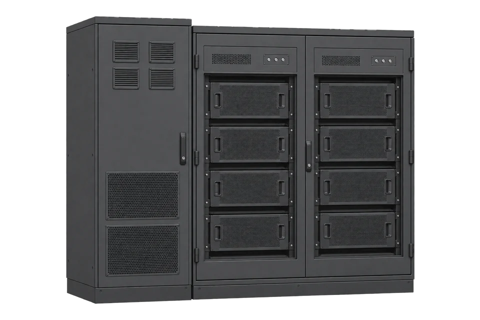
TESVOLT TS-I HV 80
Commercial battery energy storage system
TS-I HV 80 is a commercial storage system that pairs TESVOLT high-voltage NMC battery cabinets with the TESVOLT PCS battery inverter and the TESVOLT Energy Manager. The Energy Manager runs a Modbus TCP server, the marketer interface, with a public register table. Edge reads its input registers for SoC, battery, grid and PV power; the holding registers are setpoints and stay unwritten.
Compatibility
Compatible with EpiSensor Edge over Modbus TCP through the TESVOLT Energy Manager
TESVOLT publishes the Energy Manager marketer interface Modbus specification, revision H.01 (03/2025), for Energy Manager version 2.0 and higher: input registers for grid, PV, self-consumption, battery power and SoC, with word order stated per register. The Energy Manager 3.2 manual sets the interface up on port 1505. Edge reads the input registers as a Modbus TCP client.
TS-I HV 80 (A-series, datasheet v.E.01) and TS-I HV 80 E / TS-I HV 100 E (datasheet v.C.02) controlled by a TESVOLT Energy Manager 2.0 or later. Site check: have the installer add the TESVOLT AG marketer interface, confirm the unit ID it answers on, and compare SoC with myTESWORLD. Read-only: the holding registers 0 to 16 are marketer setpoints and watchdogs and stay unwritten.
Connect it with
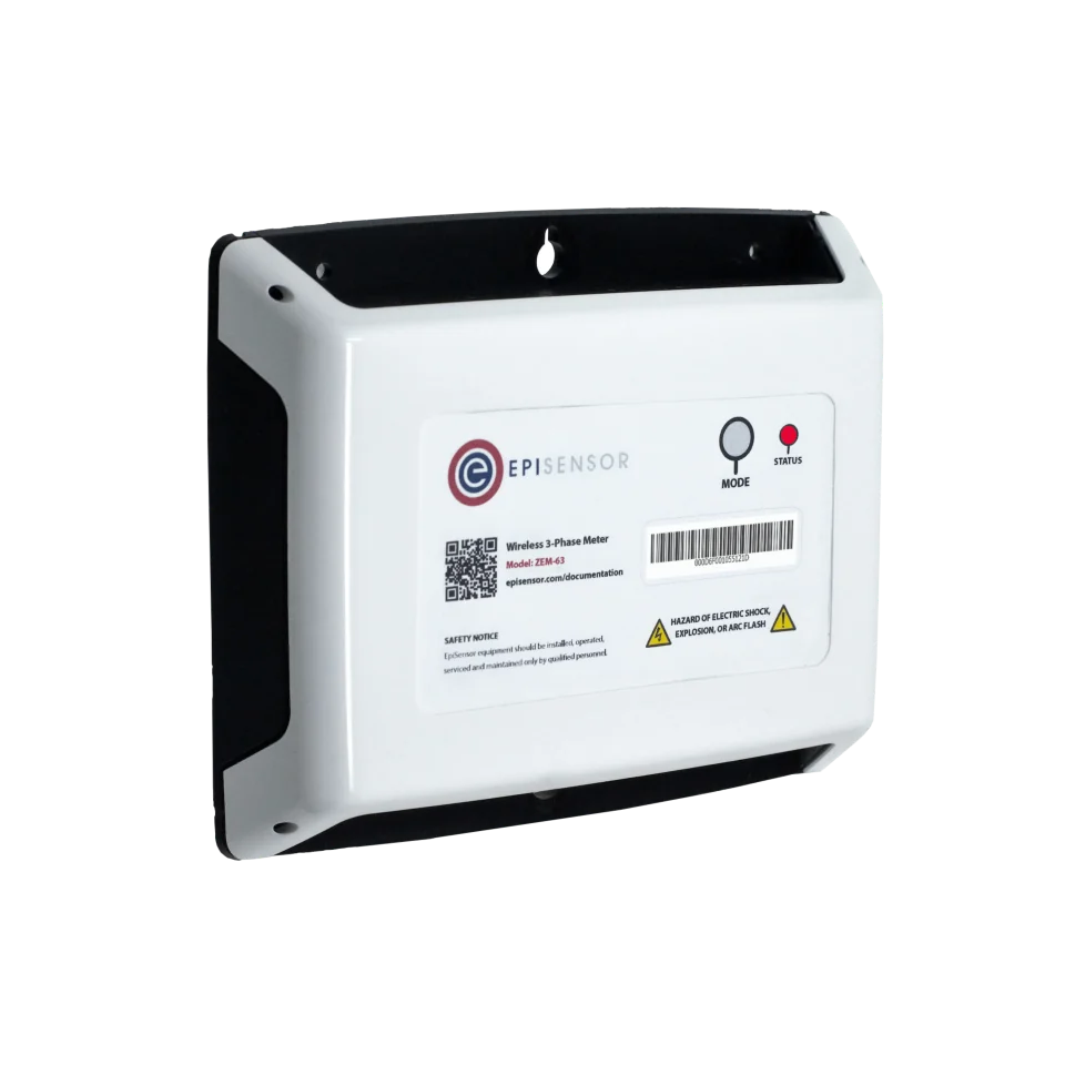

When the TESVOLT Energy Manager has the TESVOLT AG marketer interface configured under External Specifications
- Modbus
- Edge
- Platforms
For charge and discharge power and energy at the 400 V AC connection, independent of the Energy Manager
- Wired
- Edge
- Platforms
Models
| Models | Interface | Route into Edge |
|---|---|---|
| TS-I HV 80 (A-series), 76 kWh per battery cabinet of 16 modules | TESVOLT PCS with 1 to 4 IPUs (75 or 85 kW each), Modbus TCP/IP, TESVOLT Energy Manager | Energy Manager marketer interface on port 1505, or a ZEM on the PCS feeder. |
| TS-I HV 80 E (type TS HV 90/10-20, 80 kWh) and TS-I HV 100 E (type TS HV 90/12-20, 96 kWh) | TESVOLT PCS with up to 16 IPUs across 4 PCS, Modbus TCP/IP; Energy Manager use needs myTESWORLD registration | Same marketer interface route. The Energy Manager treats master/slave battery systems as one storage system, so the interface reports system totals. |
| TS HV 30-80 E with SMA Sunny Tripower Storage X, and other TESVOLT ranges | Different inverter; the Energy Manager still owns the system | The marketer interface is an Energy Manager feature, but take hardware ratings from that system's own datasheet. |
Specifications
TS-I HV 80 combines TESVOLT battery cabinets with an integrated three-phase battery inverter, the TESVOLT PCS, and the TESVOLT Energy Manager. The PCS takes up to four IPU inverter modules and runs in parallel with up to five other PCS systems.3
- Battery, TS-I HV 80
- 76 kWh per cabinet (16 modules), Samsung SDI NMC prismatic, 761 to 930 V DC, 1C3
- Battery, E-series
- TS-I HV 80 E 80 kWh at 810 V nominal; TS-I HV 100 E 96 kWh at 972 V nominal4
- Energy Manager
- IP20, indoor; -25 to +55 °C; 2 x RJ45 Ethernet (LAN 1 local, LAN 2 dedicated Modbus) and RS-4852
Interface
Documented measurements and integration boundaries for TS-I HV 80.
- Address convention: the specification prints a zero-based ADDRESS column and a one-based REGISTRY column. Send the ADDRESS: SoC at ADDRESS 9 is REGISTRY 10.
- Word order: a single register is big-endian. For 32-bit values the table names the low word and the high word; on every pair the low word is at the lower address.
- Input registers, FC04, read only: instantaneous power of the mains connection at 0 (low) and 1 (high), integer in W; PV power at 5 and 6; self-consumption power at 7 and 8; PV plant power at 30 and 31.
- Battery, input registers: state of charge at 9 (low) and 10 (high) as a float in %; battery charge/discharge power at 11 and 12 as an integer in W; possible maximum charging power at 32 and 33, possible maximum discharging power at 34 and 35, both W; storage capacity at 36 and 37 in Wh.
- Grid operator limit, input registers: maximum power value from the grid operator (EISMAN) at 3 and 4, integer in W.
- Error word, input register 100: 0x0000 no error, 0x0001 PV system error, 0x0002 battery system error, 0x0004 mains connection recording error, 0x0008 PV recording error, 0x0010 self-consumption recording error, 0x0020 SoC recording error.
- Sign and type: the specification calls the power values integer without stating whether they are signed or which direction is positive. Confirm the sign of mains and battery power against myTESWORLD under a known charge and a known import.
- Mirrored setpoints at input registers 20 to 27 show what the marketer has requested; they are not measurements.
- Holding registers 0 to 16 are read/write marketer setpoints, nominal powers and watchdogs (written about every minute during curtailment). Edge does not write them; control needs the site owner's, the marketer's and TESVOLT's agreement and is outside this guide.
Assessment
TS-I HV 80 and TS-I HV 80 E / 100 E systems controlled by a TESVOLT Energy Manager 2.0 or later, read through the marketer interface on port 1505. Marketer control, expert strategies and the dedicated APU network are excluded.
- InteroperabilitySupported with conditions
- Register addresses, data types, units, access rights and word order are public, and the manual gives the port. The unit ID and the sign of the integer powers are not stated.12
- AccuracySupported with conditions
- SoC, battery power, mains, PV and self-consumption power and storage capacity are separate points with an error word for each recording path. Energy counters are not part of the interface.1
- SecuritySupported with conditions
- TESVOLT asks for the Energy Manager to sit in a separate subnet or VLAN behind a firewall, with remote access over an encrypted VPN. The specification documents no client authentication and the holding registers accept writes.12
- ReliabilitySupported with conditions
- Error word 100 flags PV, battery and recording failures, and the watchdog design returns control to local operation after 5 minutes without a marketer value. The manual asks for fixed IP leases so a unit does not drop off.12
- RuggednessLimited
- Battery cabinets, PCS and Energy Manager are IP20 for indoor installation; the PCS operates from 0 to 40 °C.234
Setup
Read state of charge at input address 9, low word first
Marketer interface specification revision H.01 lists state of charge of the battery at ADDRESS 9 (low word) and ADDRESS 10 (high word), input registers, float, %, read only, and charge/discharge power of the battery storage at ADDRESS 11 and 12 as integer W. The response bytes are a synthetic decoder check, not a captured Energy Manager reply.
- Target
- Energy Manager IP address, TCP port 1505, the unit ID confirmed with the installer
- Request PDU
- 04 00 09 00 02: FC04, ADDRESS 9 (REGISTRY 10), two registers
- Synthetic response PDU
- 04 04 00 00 42 97: ADDRESS 9 holds 0x0000 (low word), ADDRESS 10 holds 0x4297 (high word)
- Decode
- High word first gives 0x42970000, an IEEE 754 float of 75.5 %
- Power read
- 04 00 0B 00 02 reads ADDRESS 11 and 12; synthetic response 04 04 30 39 00 00 gives low 0x3039 and high 0x0000, so 12345 W
- Wrong order
- Read high word first by mistake, the SoC bytes become 0x00004297, a float of about 0, which shows the order is reversed
- Acceptance
- Keep the points when SoC matches myTESWORLD and error word 100 reads 0x0000 or has bit 0x0020 clear.
Acceptance: A matching SoC confirms port, unit ID, address column and word order together. Settle the sign of battery and mains power next.
-
Add the marketer interface on the Energy Manager
In the Energy Manager, the installer opens Device Configuration > External Specifications, selects Configure External Specifications and chooses TESVOLT AG marketer interface. The List Address is the Energy Manager's own IP address with port :1505. TESVOLT's manual then has an expert strategy select Marketer interface as the energy service for a PV or battery actuator group, which hands those actuators to the marketer. For read-only monitoring, agree with the installer whether that step is wanted, and check that the input registers answer before relying on them.
-
Connect Edge on the local network
Connect the Gateway to the LAN 1 side of the Energy Manager, not to the dedicated Modbus network on LAN 2. TESVOLT asks for LAN 1 to be separated from the internal network, for example as a VLAN or guest network behind a firewall, so place the Gateway in that segment.
-
Read the input registers
Create a Modbus TCP connection to the Energy Manager IP address on port 1505. The specification does not name a unit ID: confirm the value with the installer or TESVOLT service and record it. Read SoC at input ADDRESS 9 with FC04, two registers, as in the worked check.
-
Assemble 32-bit values low word first
For each pair, take the register at the lower address as the low word: value = high x 65536 + low. Decode SoC as a 32-bit float from the same two words. Read each pair in one request so both halves come from the same sample.
-
Settle signs and errors
Compare mains power at 0 and 1 and battery power at 11 and 12 with myTESWORLD during a known charge and a known import to fix each sign. Read error word 100 with every poll; a set bit means the related value is not being recorded and should be shown as unavailable.
Common questions
- Can Edge read the TESVOLT battery APU directly?
- The Energy Manager reaches the master APU over Modbus TCP on port 502, but TESVOLT publishes no register list for the APU. Read the marketer interface instead, and leave the dedicated network to the Energy Manager.2
- What word order does the TESVOLT marketer interface use?
- Single registers are big-endian. For 32-bit values the specification names the low word and high word of each pair, and in every pair the low word sits at the lower address.1
- Does reading the interface change how the storage system runs?
- Edge reads only input registers. In TESVOLT's design, a marketer changes operation by writing the holding registers, and an expert strategy decides which actuators follow the marketer interface. TESVOLT also notes that firmware updates can change the communication protocol, so repeat the SoC check after one.12
Related devices
Sources
- TESVOLT Energy Manager marketer interface: Modbus specifications, revision H.01, 03/2025 (opens in a new tab) (PDF)
- TESVOLT Energy Manager 3.2 manual, RD_TI_093_E_251117, revision I.01, 11/2025 (opens in a new tab) (PDF)
- TS-I HV 80 datasheet, RD.TI.016.E.ENG, version E.01 (opens in a new tab) (PDF)
- TS-I HV 80 E / TS-I HV 100 E technical datasheet, RD.TI.075.E.en-US, version C.02 (opens in a new tab) (PDF)
Further reading
- ApplicationBattery storage performance monitoring
- ApplicationBattery demand response
- GuideBESS, BMS, EMS and PCS roles
- ToolModbus register decoder
- GuideINTILION scalepac
- GuideHuawei LUNA2000-241-2S1
- ToolModbus register address converter
- ToolRS-485 termination and bias
- ProtocolModbus devices and register maps
- CategoryBattery systems and controls
Product names and trademarks belong to their owners. Publication does not imply endorsement or a commercial relationship.