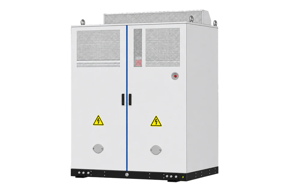
SMA Sunny Central Storage UP
Commercial and utility battery energy storage system
Sunny Central Storage UP spans SCS 3450 UP to SCS 3950 UP, with up to 3,960 kW and 1,500 V DC. SMA documents an Ethernet Modbus server: inverter input registers use unit ID 3 and FC04. Start with DC voltage and AC power, compare them with the local display and retain the existing plant controller.
Compatibility
Compatible with EpiSensor Edge over Modbus TCP
SMA document MODBUS-SCS-NSD-xxx-TI-en-21 covers the UP models from firmware 10.02.xx.R and defines the inverter as an Ethernet Modbus server with addresses, function codes, units and decoding. Edge reads the inverter input registers at unit ID 3 with FC04 as a Modbus TCP client.
SCS 3450 UP, 3600 UP, 3800 UP and 3950 UP in datasheet SCS-UP-DS-en-23. Site check: confirm the configured endpoint and installed profile, and compare a DC-voltage read with the local display. No control or protection authority is transferred.
Connect it with
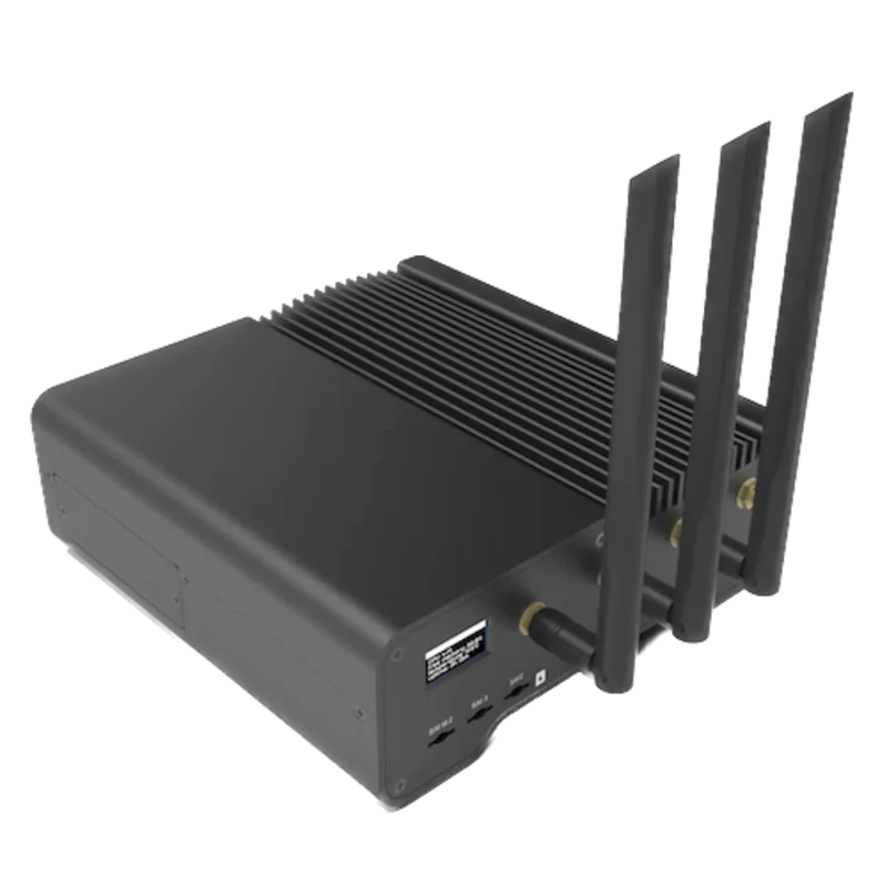
For read-only monitoring of the standard inverter profile at unit ID 3
- Modbus
- Edge
- Platforms
Models
| Models | Interface | Route into Edge |
|---|---|---|
| SCS 3450 UP / SCS 3600 UP | 3,450 or 3,620 kW nominal at 25 °C; 600 or 630 V AC | Use the inverter Modbus server and unit ID 3 for the documented input registers; the existing controller continues to own setpoints. |
| SCS 3800 UP / SCS 3950 UP | 3,800 or 3,960 kW nominal at 25 °C; 660 or 690 V AC | Do not transfer voltage or power limits from the lower-voltage models. |
Specifications
The current datasheet covers four European type designations from 3,450 to 3,960 kW nominal output at 25 °C and DC operation up to 1,500 V.2
- Model range
- SCS 3450 UP, 3600 UP, 3800 UP and 3950 UP2
- Nominal output
- 3,450 to 3,960 kW at 25 °C, depending on exact type2
- DC range
- Model-dependent lower limit from 880 to 1,003 V; 1,500 V maximum2
- Published communications
- Ethernet, Modbus Master and Modbus Slave; Modbus TCP to SMA string monitor2
- Environment
- Electronics IP54; -25 to +60 °C standard, optional to -40 °C; derating applies2
- Control scope
- Grid-forming, current boost and black-start readiness are optional engineered functions, not monitoring permissions2
Interface
Documented measurements and integration boundaries for Sunny Central Storage UP.
- Unit ID 3, FC04: DC voltage at address 0, total AC active power at 28 and grid frequency at 38. Each uses two registers and signed S32 decoding; divide voltage by 10 and frequency by 100, while power is directly in kW.
- Battery communication, inverter control, plant controller, string monitor, site meter and protection relay remain distinct sources.
- Unit ID 2 contains system data, unit ID 3 the inverter, and unit ID 100 the optional user-defined profile. A battery profile is separate; inverter data is not automatically whole-site or battery-rack telemetry.
- No grid-forming, current boost, black start, reactive-power, protection or battery command is approved by this guide.
Assessment
SCS 3450 UP, 3600 UP, 3800 UP and 3950 UP in datasheet SCS-UP-DS-en-23. Confirm exact type designation, firmware, battery, controller and medium-voltage system. No control or protection authority is transferred.
- InteroperabilitySupported with conditions
- SMA specifies server roles, unit IDs, FC04 input registers and signed decoding. Installed profiles and concurrent-client limits still need a site check.3
- AccuracySupported with conditions
- DC voltage, AC power and frequency have documented addresses, signed types, scales and units. Suitable starting points for operational monitoring; SMA states no billing accuracy.3
- SecurityNot yet assessed
- Authentication, encryption, roles and read-only privilege separation for an independent client are not defined in the retained public sources.12
- ReliabilityLimited
- System operating limits are published, and SMA limits instantaneous reads to 10 per second. SMA publishes no client recovery, stale-data or concurrent-client figures; timestamp each read.12
- RuggednessSupported with conditions
- The datasheet publishes enclosure, cooling, temperature, humidity and altitude limits; the project must apply model-specific derating.12
Setup
-
Confirm the delivered system
Record every enclosure, battery rack, PCS, BMS, EMS, meter and controller identity, plus firmware, software, network and contract revisions.
-
Map authority before data
Document which system owns charge and discharge, protection, fire and life safety, grid control, market dispatch, settlement, warranty and emergency response.
-
Read DC voltage with FC04
Use the inverter’s configured Modbus endpoint, unit ID 3 and FC04 (Read Input Registers), starting address 0, length 2. These are direct protocol addresses: do not add 30001 or subtract one. Decode the two words as signed S32, high word first, and divide by 10 for volts. For an illustrative response of words 0 and 8500, the result is 850.0 V. Compare it with the inverter’s DC-voltage display.
-
Compare AC power and keep the controller
Read unit ID 3, FC04, address 28, length 2 for InvMs.TotW: signed S32, scale 1, kW. Compare the value and direction with the inverter display and its AC feeder meter during existing operation. Use a slow monitoring interval; SMA limits instantaneous reads to 10 per second. Leave plant setpoints and the separate battery communication unchanged.
Common questions
- Is the Sunny Central Storage UP compatible with EpiSensor Edge?
- Yes, over Modbus TCP. SMA publishes a concrete inverter server map, so Edge starts with the FC04 reads in this guide at unit ID 3. Record the configured endpoint and profile with the point list.3
- Can Edge use the string-monitor connection?
- Not automatically. The datasheet names that route for SMA string-monitor communication; it does not define a general third-party telemetry service.2
- Can this guide enable grid-forming or black start?
- No. Those optional functions require project engineering, grid approval, protection studies and an authorised plant controller.2
Related devices
Sources
- Sunny Central Storage UP product page (opens in a new tab)
- Sunny Central Storage UP datasheet SCS-UP-DS-en-23 (opens in a new tab) (PDF)
- Sunny Central Storage Modbus interface MODBUS-SCS-NSD-xxx-TI-en-21 (opens in a new tab) (PDF)
Further reading
- ApplicationBattery demand response
- GuideBESS, BMS, EMS and PCS roles
- ToolBattery autonomy calculator
- ToolModbus register address converter
- ToolModbus data decoder
- ToolRS-485 termination and bias
- GuideModbus RS-485 commissioning
- ManufacturerSMA devices
- ProtocolModbus devices and register maps
- CategoryBattery systems and controls
Product names and trademarks belong to their owners. Publication does not imply endorsement or a commercial relationship.