SMA Sunny Island 6.0H-13
Battery inverter
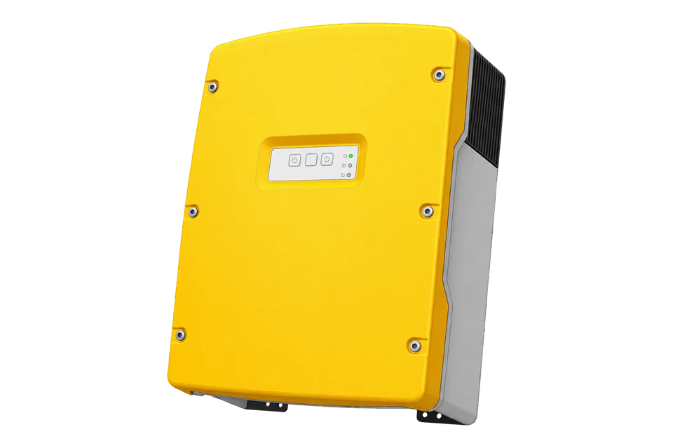
Sunny Island 6.0H-13 is a battery inverter rather than a PV string inverter. Its local interface exposes battery and operating measurements through the SMA register profile. In a cluster, the master and system topology determine which values are available; a single inverter power reading must not be labelled as an entire multicluster total.
- Modbus TCP
Battery inverter
Compatibility
Documented local Modbus TCP interface
The manufacturer documents the read interface. Edge requires an explicitly configured client and verified point definitions; this guide is not a ready-made device template.
Exact model SI6.0H-13 from firmware 3.30.12.R, as covered by SI-Modbus-BA-en-12. The -12 generation, 4.4M and 8.0H are distinct models. Monitoring only; grid management, battery limits and remote power commands are outside this guide.
Connect it with
-
Gateway ZGW-20From €899 ex VAT Configure Gateway
-
Evaluation Gateway on a Raspberry Pi Edge with one device licensedFree Set up Evaluation Gateway on a Raspberry Pi

For an already commissioned Sunny Island system
- Modbus
- Edge
- Platforms
Models
| Models | Interface | Route into Edge |
|---|---|---|
| SI6.0H-13 | Sunny Island 6.0H, generation -13; device code 9475 | Minimum covered firmware is 3.30.12.R. Confirm the nameplate and code before adding points. |
| SI6.0H-12 | Earlier generation; device code 9333 | A similar power rating does not establish the same firmware scope. |
| Single-cluster and multicluster systems | Master/slave and aggregate measurement paths differ | SMA recommends Data Manager M for reading aggregate multicluster power, energy and state of charge. |
Specifications
- Exact scope
- SI6.0H-13; firmware 3.30.12.R or later covered by the cited manual1
- Protocol
- SMA Modbus profile only; not SunSpec1
- Default endpoint
- TCP port 502, SMA unit ID 3; confirm the configured values2
- Read functions
- FC03/FC04 according to SMA protocol; whole multi-register values2
- Address convention
- SMA table addresses are PDU addresses; do not strip a 4xxxx prefix or subtract one2
- Installation envelope
- IP54 and -25 to +60 °C are documented, with mounting, cooling and derating requirements in the operating manual.3
Interface
Documented measurements and integration boundaries for Sunny Island 6.0H-13.
- Device type at SMA address 30053, U32 TAGLIST; 9475 identifies SI6.0H-13.
- Battery state of charge at 30845, U32 FIX0, in percent.
- Battery current at 30843, signed 32-bit FIX3; divide the raw integer by 1,000.
- Battery voltage at 30851, U32 FIX2; divide by 100 for volts.
- Inverter power at 30775, signed 32-bit FIX0 in watts, with operating state at 30201.
- Generator status is an enumerated state, not a measurement of generated energy.
Assessment
SI6.0H-13 local reads, manual revision 12 and its stated firmware scope.
- InteroperabilityWell supported
- Public model-specific identity and measurement addresses complement the general SMA protocol. The interface is SMA-specific, not SunSpec.12
- AccuracySupported with conditions
- Battery scales, types and operating states are documented. Cluster totals require the appropriate master or aggregation path.1
- SecuritySupported with conditions
- SMA requires segmentation and warns against port forwarding. Ordinary Modbus reads do not gain encryption or authentication from the web login.1
- ReliabilitySupported with conditions
- Operating-state and unavailable-value definitions support explicit fault and stale-data handling; the host must preserve those states.12
- RuggednessSupported with conditions
- IP54 and -25 to +60 °C are documented, with mounting, cooling and derating requirements in the operating manual.3
- ScalabilitySupported with conditions
- The manual distinguishes single and multicluster reading and recommends a Data Manager for aggregates. Per-inverter power must not be summed indiscriminately.1
- LifecycleSupported with conditions
- The manual identifies model generations and minimum firmware, providing a reproducible basis for revalidation after updates.1
Setup
Identify SI6.0H-13 before reading battery current
Manufacturer table values and synthetic decoder fixtures. These bytes were not captured from an operating inverter.
- Function
- FC03 Read Holding Registers
- Identity address and length
- 30053 decimal = 0x7565; two registers; U32 TAGLIST
- Request PDU
- 03 75 65 00 02
- Expected model data
- 00 00 25 03 = 9475, the SI6.0H-13 device code
- Current point
- 30843 decimal = 0x787B; two registers, S32 FIX3
- Synthetic current data
- FF FF CF 2C = -12500; divide by 1000 = -12.5 A
- Unavailable values
- S32 0x80000000 and U32 0xFFFFFFFF must remain unavailable
- SOC and voltage
- SMA-profile FC03 at wire 30845, quantity 2 reads SOC U32 FIX0 in %. Wire 30851, quantity 2 reads battery voltage U32 FIX2 in V. Read each complete value as high word then low word. Synthetic SOC data 00 00 00 49 gives 73%; voltage is raw ÷100. U32 0xFFFFFFFF is unavailable, not zero.
- AC power
- SMA-profile FC03 wire 30775, quantity 2 reads AC power S32 FIX0 in W. This is inverter AC power, not DC battery power or whole-site import/export. Preserve the signed value and compare its direction with the local inverter view. S32 0x80000000 is unavailable.
Acceptance: Accept the model only when its code and nameplate agree. The negative current fixture checks signed decoding; establish the installed system’s charge/discharge sign against its own interface before labelling direction.
-
Confirm model, firmware and topology
Record SI6.0H-13, its firmware and the cluster master. The manual covers this model from 3.30.12.R. For a multicluster installation, identify whether the required measurement is per-inverter or a Data Manager aggregate.
-
Enable and restrict local reads
In External communication, enable the Modbus TCP server using an authorised account. Record the IP address, TCP port and unit ID. Restrict access to the monitoring host; enabling Modbus exposes a writable interface as well as reads.
-
Read the model identifier first
Read two holding registers at PDU address 30053. The U32 device type must be 9475 and agree with the nameplate. Stop on a different code instead of applying a nearby Sunny Island model map.
-
Add battery quantities with their declared scales
Read complete two-register values for SOC, current and voltage. FIX3 current is a signed integer divided by 1,000; FIX2 voltage is unsigned divided by 100. Reject type-specific unavailable values before scaling.
-
Compare the same measurement boundary
Compare the local battery display and inverter power at the same time. Verify sign under a known charge or discharge condition. Retain operating state, stale timestamps and communication errors; do not turn missing readings into zero. Repeat these checks after firmware changes.
Related devices
Sources
- Sunny Island Modbus user manual, revision 12 (opens in a new tab) (PDF)
- SMA Modbus technical information, revision 10 (opens in a new tab) (PDF)
- Sunny Island -13 operating manual, revision 19 (opens in a new tab) (PDF)
Further reading
Product names and trademarks belong to their owners. Publication does not imply endorsement or a commercial relationship.