Janitza UMG 806
DIN-rail power analyser
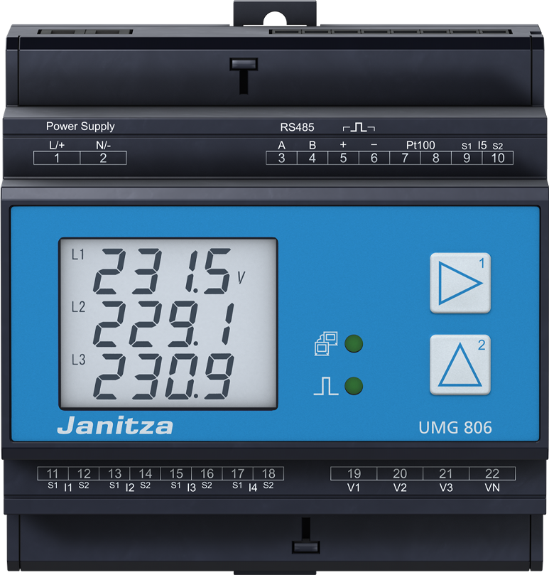
The UMG 806 combines electrical measurements, residual-current monitoring and a Pt100 input in a five-module DIN-rail enclosure. Its built-in RS-485 port serves Modbus RTU; Ethernet requires the separate 806-EC1 communication module. Janitza's address list puts common voltage, current, power and energy values in the 19000 range. This guide covers the standard 1 A or 5 A CT model and identifies where the 333 mV UMG 806-LP differs.
Compatibility
Compatible with EpiSensor Edge over Modbus RTU or optional Modbus TCP
Edge reads the standard UMG 806 through its RS-485 Modbus RTU interface using a ZMB-31 wireless Modbus Interface or an approved serial interface at the Gateway. A fitted 806-EC1 provides the Ethernet Modbus TCP route.
Standard UMG 806 with 1 A or 5 A CT inputs, using the July 2024 manual and address list for firmware 2.0.32 as the starting documents. The LP model uses 333 mV sensors. Site check: record the exact label, firmware and fitted module, then compare imported voltage, current and energy with the display before expanding the polling list. Read-only monitoring.
Connect it with
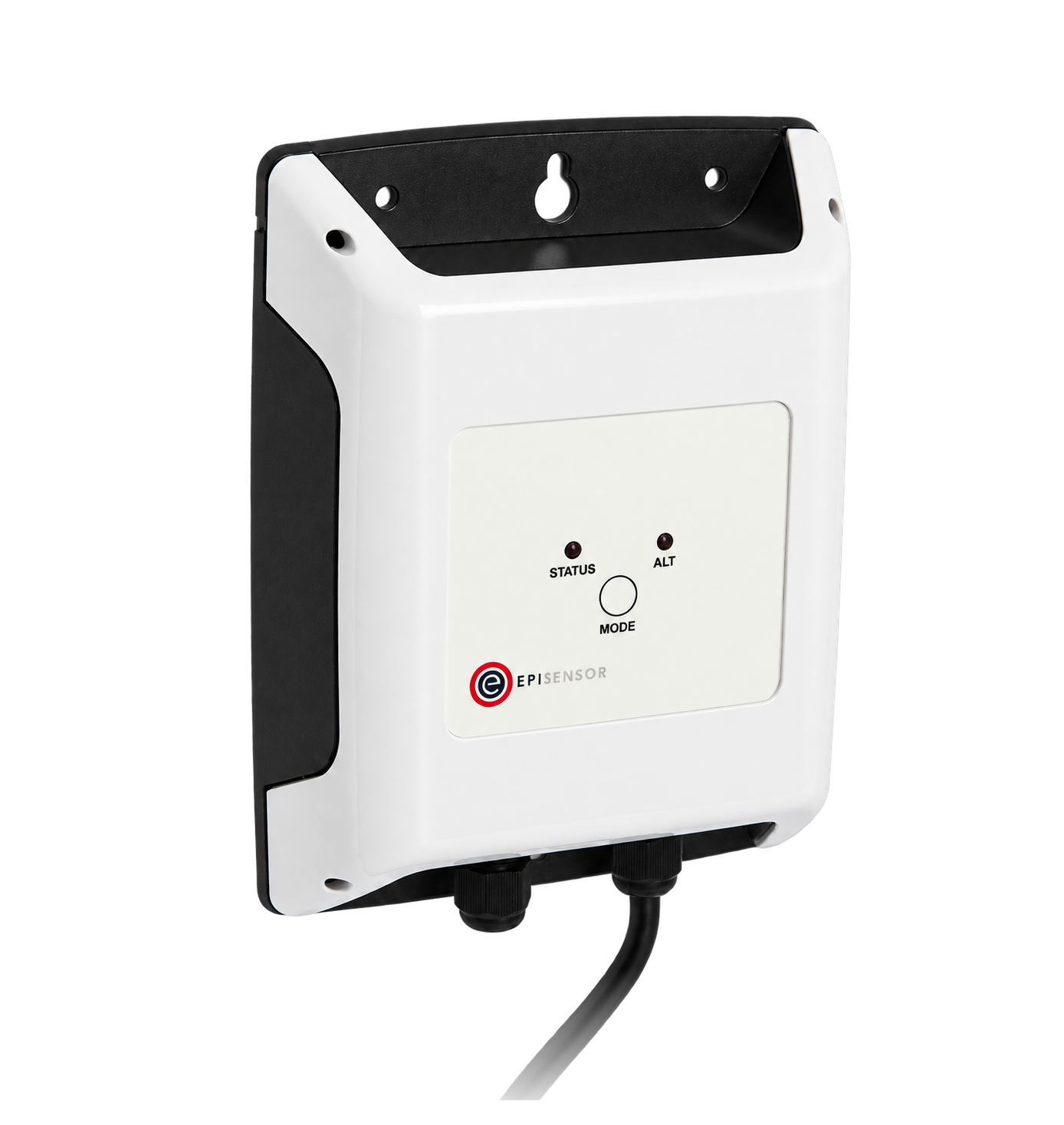
For an analyser in a panel where a wireless link avoids a data cable back to the Gateway
- Modbus
- Wireless
- Edge
- Platforms
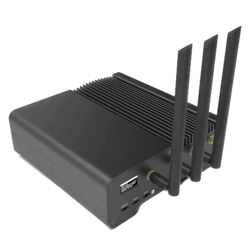
When the Gateway has an approved serial interface near the analyser or on the same wired RS-485 bus
- Modbus
- Edge
- Platforms
Only when the optional 806-EC1 communication module is fitted
- Modbus
- Edge
- Platforms
Models
| Models | Interface | Route into Edge |
|---|---|---|
| UMG 806 | Four current inputs for 1 A or 5 A CT secondaries, a separate residual-current input, Pt100 input and RS-485 Modbus RTU. | Use the built-in serial interface, or the optional 806-EC1 for Ethernet. Record the primary and secondary CT settings for I1 to I3 and I4 separately. |
| UMG 806-LP | Low-power current-transformer inputs with a fixed 333 mV secondary setting. | Identify the LP label before selecting sensors. A shared address list does not make its physical inputs interchangeable with the standard 1 A or 5 A model. |
Specifications
This is a compact circuit analyser with separate electrical, residual-current and temperature measurements. Ethernet is an expansion choice, while the standard serial port is already usable for Edge monitoring.12
- Current inputs
- Four channels for 1 A or 5 A CTs; published measurement range 0.005 to 6 A RMS. The LP variant instead uses 333 mV sensors.13
- Residual current and temperature
- Separate I5 residual-current input and a Pt100 temperature input. These are different input functions from the four phase/neutral CT channels.1
- Serial interface
- Two-wire RS-485 Modbus RTU, up to 115.2 kbit/s. Device addresses 1 to 247. The unit has no internal termination resistor.13
- Ethernet
- The optional 806-EC1 adds Modbus TCP and SNMP V2c. It is not a port on the base analyser.1
- Supply and enclosure
- 100 to 300 V AC at 50/60 Hz or 100 to 300 V DC. Five-module DIN-rail enclosure, approximately 90 × 90 × 63.5 mm, IP20.1
- Operating environment
- Weather-protected stationary use, -25 to +70 °C, non-condensing humidity and pollution degree 2. Provide a suitable panel enclosure.1
Interface
Documented measurements and integration boundaries for UMG 806.
- The common-reading table on page 4 gives L1-N, L2-N and L3-N voltage at addresses 19000, 19002 and 19004, and line-to-line voltage at 19006, 19008 and 19010. These entries are labelled float and V.
- Current I1 to I4 is at 19012, 19014, 19016 and 19018, labelled float and A. The fourth current input has its own transformer settings.
- Per-phase active power is at 19020, 19022 and 19024; the three-phase sum is at 19026. The published unit is W. Convert W to kW once when presenting it.
- The table gives apparent power at 19028 to 19034 in VA, fundamental reactive power at 19036 to 19042 in var, per-phase cos phi at 19044 to 19048 and frequency at 19050 in Hz. Cos phi is the fundamental quantity identified by the source.
- Total active energy at 19060 and consumed active energy at 19068 are labelled float and Wh. Keep the unit distinct from kWh and distinguish total energy from consumed energy.
- The address list contains writable configuration and reset entries as well as measurements. Build a read-only polling list from RD entries; do not import reset commands or write the energy registers. Retain raw register words and check the client address convention and float decoding against the display.
Assessment
UMG 806 standard CT variant, July 2024 manufacturer manual and address list. Ratings describe published integration evidence and installation conditions.
- InteroperabilitySupported with conditions
- The standard RTU interface and published typed address table provide an open read path. Ethernet depends on the optional 806-EC1, and client addressing and multi-register decoding need a display comparison.12
- AccuracySupported with conditions
- The sources distinguish four 1 A or 5 A channels, separate residual-current and Pt100 inputs, and the LP variant. Published quantities and units support circuit monitoring when the input and transformer settings match the installation.123
- SecuritySupported with conditions
- A configuration password is documented, with 0000 as the factory setting. The map includes writable reset and configuration points. Use a protected bus or network and read-only polling; the cited interface descriptions provide no encrypted Modbus transport.123
- ReliabilitySupported with conditions
- The manual gives supply tolerance, environmental limits and troubleshooting for communication and measurement errors. Reliable polling depends on correct termination, matching serial settings and a single bus client.13
- RuggednessSupported with conditions
- The manufacturer specifies IP20, stationary weather-protected use and -25 to +70 °C. A suitable panel must provide the protection the installation requires.1
Setup
-
Identify the input variant
Record UMG 806 or UMG 806-LP from the label, the installed firmware and any 806-EC1 module. Match the current sensors to the physical input variant before planning the connection.
-
Record wiring and transformer ratios
Check the configured three-phase four-wire, three-phase three-wire or single-phase wiring mode. Record the primary and secondary CT settings for I1 to I3 and separately for I4, plus any voltage-transformer ratio.
-
Match the serial settings
The installation instructions identify parameter 200 as device address, 201 as baud rate, 202 as data frame and 203 as RTU server or gateway mode. Record their current values. Match the Edge client to them and check the two end terminations.
-
Compare one quantity before adding a block
Start with one displayed voltage from the common-reading table. Preserve the raw words, configured client address convention, float order and unit alongside the decoded reading. Resolve any mismatch before adding phase currents, power and energy.
-
Check the energy interval
Record the displayed and imported consumed-energy values at the same start and end times. Compare their changes with the correct Wh or kWh conversion. Keep this check separate from an instantaneous power comparison.
Common questions
- Does every UMG 806 have Ethernet?
- No. The standard device has RS-485. The optional 806-EC1 communication module adds Ethernet Modbus TCP and SNMP V2c.
- Can 333 mV sensors replace 1 A or 5 A CTs?
- The UMG 806-LP is the 333 mV input variant. Identify the installed model and use the sensors specified for that input; a common register list does not make the physical inputs interchangeable.
- Why does an energy read look a thousand times too large?
- The common-reading table labels these energy values in Wh. Divide by 1000 when displaying kWh, and check whether the client already performs that conversion before applying another one.
Related devices
Sources
- UMG 806 user manual and technical data, 2.064.005.6.a, July 2024, from firmware 2.0.32 (opens in a new tab) (PDF)
- UMG 806 and UMG 806-LP Modbus address list, 2.064.008.2.a, July 2024, firmware 2.032 and higher (opens in a new tab) (PDF)
- UMG 806 and UMG 806-LP installation instructions, firmware 2.0.32, German and English (opens in a new tab) (PDF)
Further reading
Product names and trademarks belong to their owners. Publication does not imply endorsement or a commercial relationship.