
Server room and rack temperature monitoring
Probes at the rack inlet and exhaust, a separate humidity transmitter, and each point’s position, history and alarms kept together in Edge.
- Measure
- Temperature at identified rack positions and relative humidity from a separate transmitter
- Sensors
- TES-21, one external temperature probe per monitoring point Probe Temperature Sensor datasheet
- On site
- ZGW-20 Gateway, Edge keeps trends and runs configured local rules Gateway datasheet
Choose the humidity instrument as well as the temperature points
The TES-21 measures temperature. Relative humidity needs a separate transmitter selected for its range, accuracy, calibration and intended mounting. The example below uses its externally powered 4–20 mA output through a mains-powered ZIO-20, so the point plan must include a qualified supply for each part. A 0–10 V transmitter needs a ZVO interface; Modbus RTU needs a ZMB interface on a suitable bus; a supported Ethernet protocol can connect to Edge directly. Agree the actual instrument, interface and power arrangement before ordering the complete system.
Hardware for rack environmental measurements
Count identified temperature positions, then add an interface for each selected humidity signal and a Gateway for the surveyed wireless coverage area.
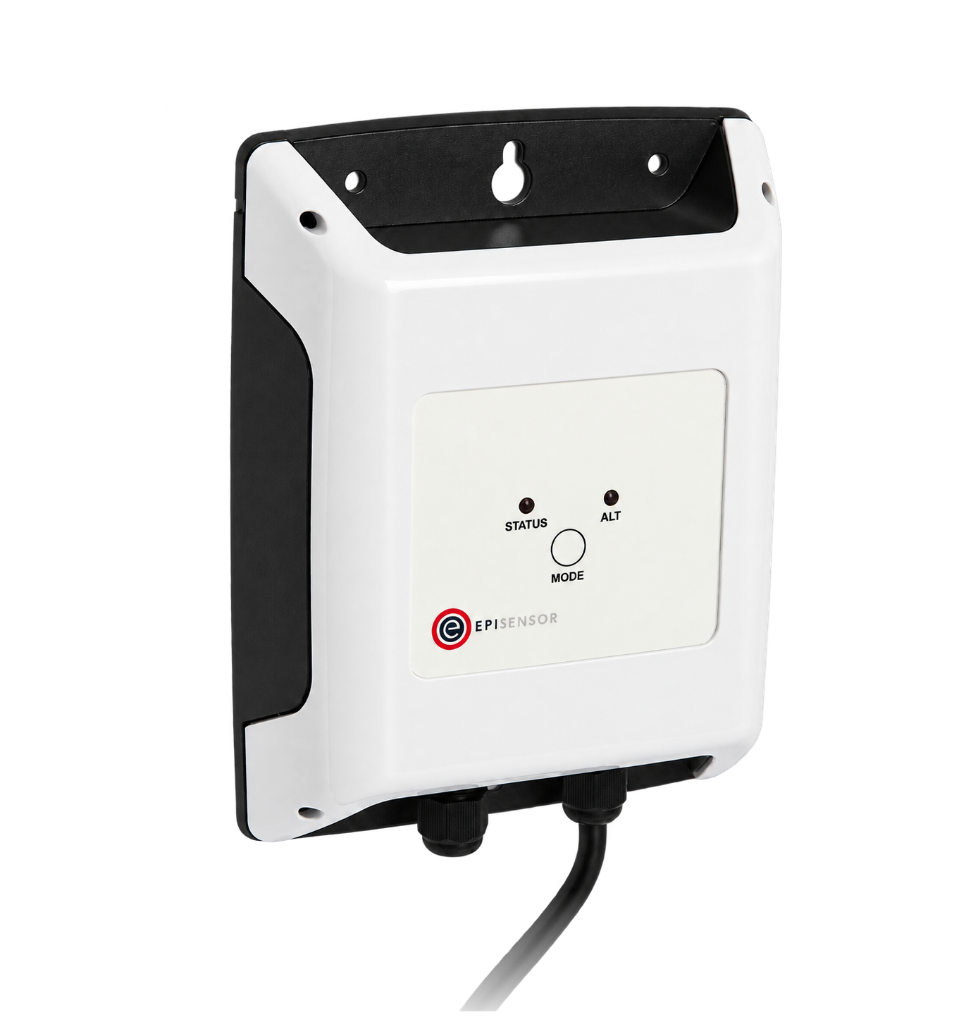
Temperature at a labelled inlet, exhaust or room reference position
1 per temperature point one steel probe, 2 m lead
 1 steel probe, 2 m lead
±0.2 °C from 0 to 70 °C, ±0.5 °C over the full −40 to 105 °C range
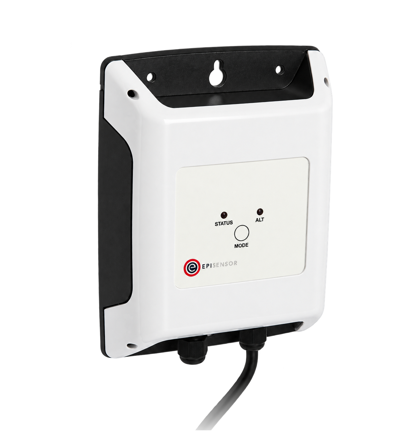
Reads the selected third-party humidity transmitter's externally powered 4–20 mA signal; the transmitter is supplied separately
1 per humidity signal one externally powered loop

Collects the wireless measurements, keeps local history and runs configured rules
1 per surveyed coverage area coverage and capacity checked on site
Plan server room temperature monitoring by rack position
Record the room, row, rack, side, height and sensor serial number for every point. Inlet, exhaust and room-reference readings answer different questions; the equipment airflow and the site's cooling design decide the locations. Keep each TES enclosure within its probe lead and agree where mains-powered ZIO units, transmitter supplies and loop wiring can be installed safely.
How rack conditions reach Edge
Temperature probes and the selected humidity transmitter feed the site Gateway through their own measurement paths.
- Wired
- Zigbee
- Edge
- Platforms
| Position | What it tells you | Reference | Sensor |
|---|---|---|---|
| Rack inlet positions | The air temperature at the selected equipment intake positions | Record height and airflow direction; keep the probe clear of surfaces that would turn an air measurement into a contact measurement DOE measurement guide | TES-21 (on this page), inlet |
| Rack exhaust positions | The temperature of air leaving the selected equipment or rack position | Label the exhaust position explicitly and do not treat it as equipment inlet temperature ASHRAE data-centre guidance | TES-21 (on this page), exhaust |
| Room reference position | A separately located room condition against which named rack positions can be interpreted | Record the reference location and height; a room reading does not establish conditions at every rack inlet DOE measurement guide | TES-21 (on this page), room reference |
| Relative humidity position | The selected transmitter's RH reading at its documented position | Record manufacturer, model, range, calibration and output scaling; ZIO-20 acquires the signal rather than measuring humidity itself Analogue Signal Sensor datasheet | ZIO-20 (on this page) |
| Measurement freshness | Whether the temperature and humidity points are still reporting | Choose expected reporting intervals and test the missing-data response for each point | ZGW-20 (on this page) |
Add points where the racks differ. Choose additional points where rack loading, airflow or containment differs. The example quantities do not establish coverage for another installation.
Assess condensation separately. Relative humidity changes with air temperature. A condensation assessment needs suitable temperature and moisture measurements, the relevant surface temperature and an agreed dew-point method; this point set does not establish that margin by itself.
Commission the installed path. Metal cabinets and changed door positions can alter the wireless path, so test with the room in its normal operating configuration. The TES-21 datasheet states accuracy but not an air-response time; commission the complete delay through the probe, reporting interval, Edge rule and notification path.
Keep rack identity, trends and missing data visible in Edge
Name points by their physical positions and configure rules around the operator's response procedure. Temperature limits and response times come from the equipment and site design.
- Compare identified positions
- Trend inlet and exhaust points together while retaining their individual names. A difference can help an investigation, but it does not on its own measure cooling capacity or airflow.
- Use explicit alarm limits
- Configure high and low limits and any delay around the documented equipment requirements. Test alarm onset, recovery and the intended operator notification path.
- Treat a silent point as missing data
- Configure activity monitoring for each expected reporting interval. An old normal reading must not stand in for a current rack condition; prove the missing-data alarm during commissioning. A reporting ZIO-20 proves only that the input device is active, not that the separate humidity transmitter and its loop are healthy, so retain the raw current and define the selected transmitter's fault-state checks separately.
- Keep local and onward evidence separate
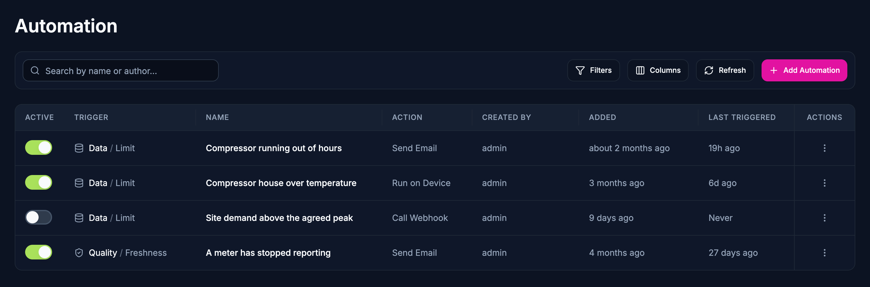
- Edge keeps the local measurements. If a BMS or monitoring platform needs them, configure the supported export and verify timestamps, point names, values and receiving-platform acceptance separately.
Commissioning checks
Complete these checks against the agreed rack drawing and the selected instruments before relying on the alarms.
-
Match every name to its installed position
Photograph each probe and RH transmitter, label the rack, side and height, and compare serial numbers with Edge.
Pass when every displayed point resolves to one documented physical position and its purpose.
-
Compare readings with a suitable reference
Record the instrument calibration details and compare temperature and RH with appropriate reference instruments at the same positions after stabilisation; account for the specified uncertainty and response time.
Pass when readings meet the agreed acceptance tolerance and any offset or uncertainty is recorded, rather than silently adjusted away.
-
Prove humidity scaling end to end
Check the transmitter's output range, loop supply and input configuration, then compare the transmitter's reference reading with the value in Edge.
Pass when the displayed RH and units match the selected instrument across the agreed commissioning checks.
-
Prove the humidity signal-failure state
Use the humidity transmitter manufacturer's documented test method to exercise its available fault indication without exceeding the ZIO-20 input range; observe the raw current, scaled value and alarm separately.
Pass when the agreed transmitter or loop fault is distinguishable from a valid RH reading, or the limitation and a separate diagnostic are recorded.
-
Test wireless reporting with rack doors closed
Observe every point with rack doors closed, normal containment and the room operating as expected; repeat at the agreed reporting interval.
Pass when the required points report consistently over the agreed observation period and any coverage changes are documented.
-
Make a point go stale
Use a controlled reporting interruption for a selected sensor and then restore it; observe the activity alarm and recovery.
Pass when the stale-data condition is visible and notified as configured, and restoration does not hide the missing interval.
-
Exercise alarm and receiver paths
Use a bounded test to exercise an agreed limit and its recovery; if exporting, compare the received values and timestamps with Edge.
Pass when the intended operator receives the alarm and recovery, and any optional platform accepts the correct point identity and reading.
Limits of this measurement
This system records selected measurement positions. Its usefulness depends on the point plan, instrument selection and a tested operational response.
- These readings do not certify cooling design, equipment operating limits, data-centre compliance or uptime.
- A separate RH transmitter, its power supply and its calibration requirements must be specified; the EpiSensor hardware list alone is not a complete humidity system.
- Relative humidity alone does not establish dew point or condensation margin; that assessment also needs suitable temperature and surface-condition evidence.
- Probe count and position are site-specific. A room average cannot establish every rack's inlet conditions.
- Local rule execution does not guarantee delivery through an unavailable external notification or platform connection.
- This guide does not establish a safety interlock or authorise automatic changes to cooling equipment.
Sources
- Data Center Energy Efficiency Measurement Assessment Kit Guide and Specification (opens in a new tab) (opens in a new tab) U.S. Department of Energy
- ASHRAE Handbook chapter: Data Centers and Telecommunication Facilities (opens in a new tab) (opens in a new tab) ASHRAE
Related
-

Data centre power monitoring and PUE inputs
Meter the facility incomer, UPS and IT supplies, and get matched energy totals for PUE and capacity reviews. -
Indoor environmental monitoring
A probe where people actually are, an outdoor reference to compare it with, and the ventilation state that explains the difference. -
Modbus meter integration for a BMS or SCADA system
A Modbus interface reads the meters and instruments on site, and Edge serves what it collects onward over Modbus TCP, MQTT or HTTP to the system that needs it.
Third-party devices for this application
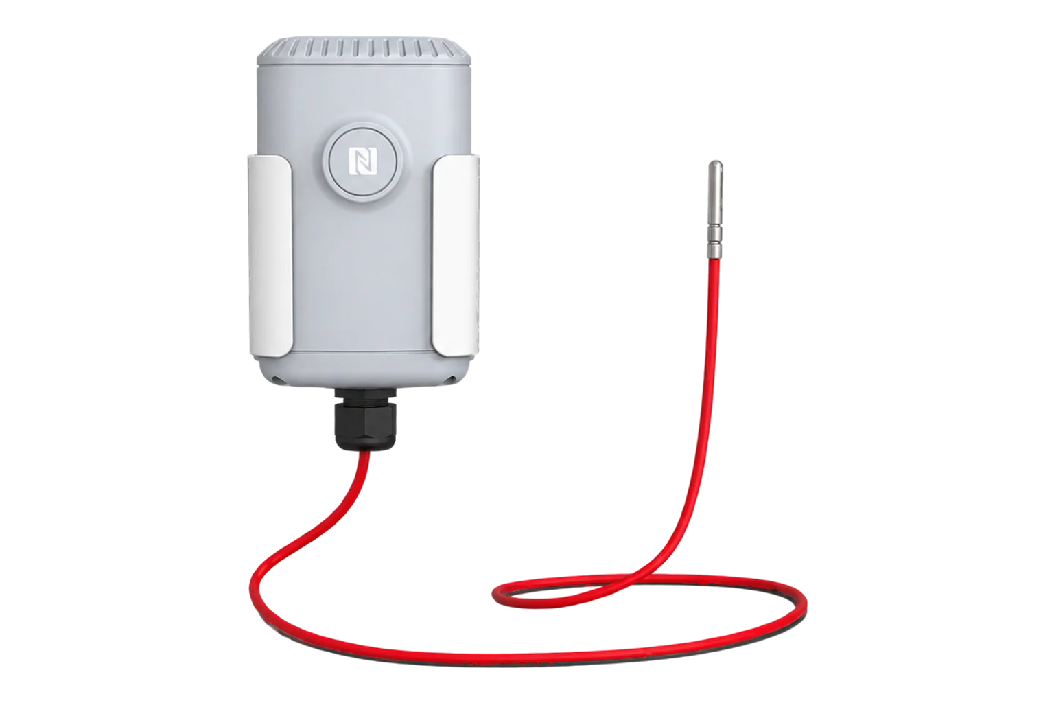
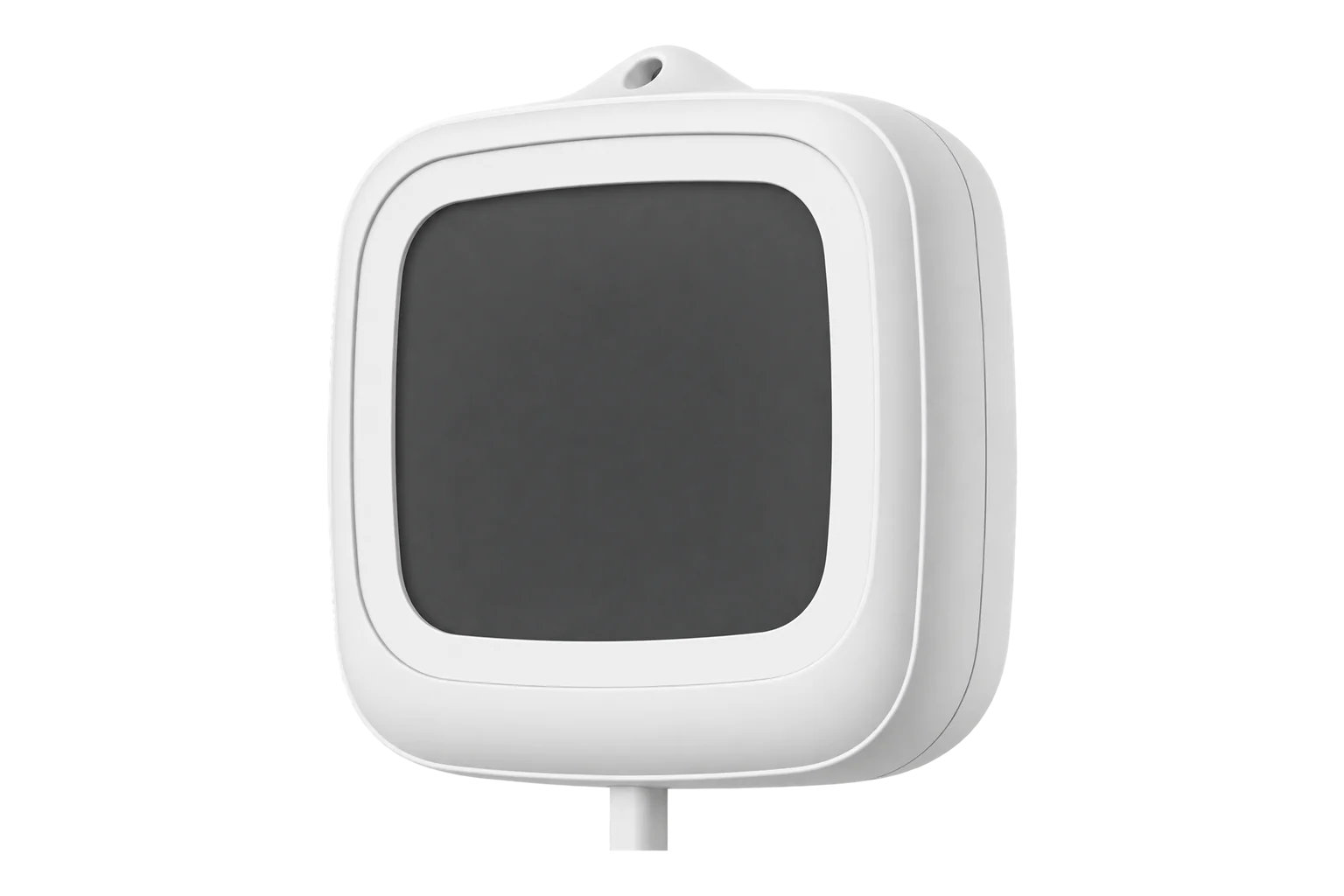
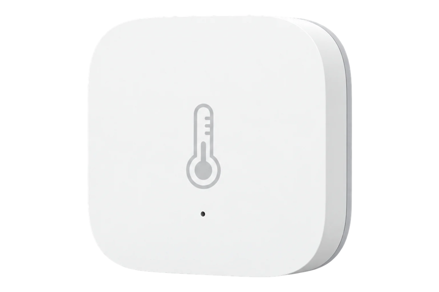
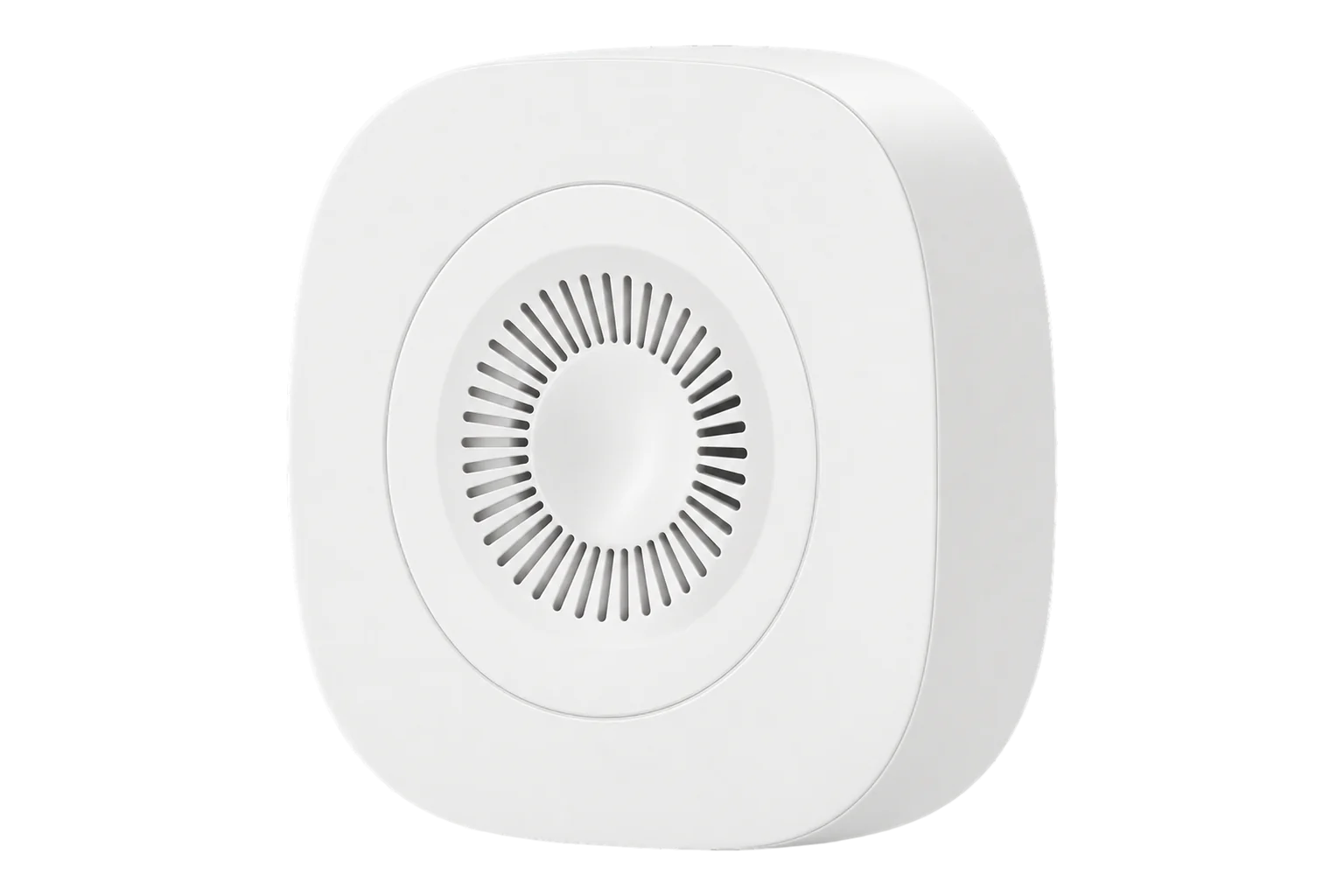
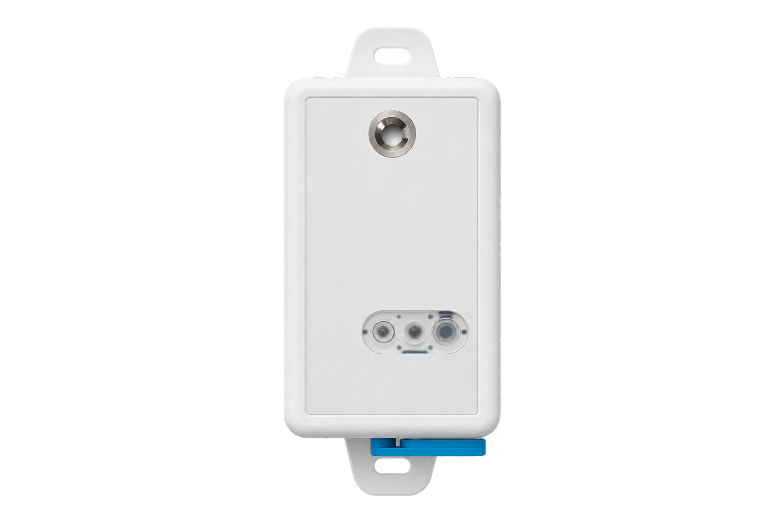
More in the Device Directory: Temperature and humidity sensors (21)
Plan the rack points and the humidity instrument
Share the rack layout, airflow arrangement and equipment limits. An engineer can then scope the temperature positions, the humidity transmitter interface, wireless coverage and the commissioning checks.