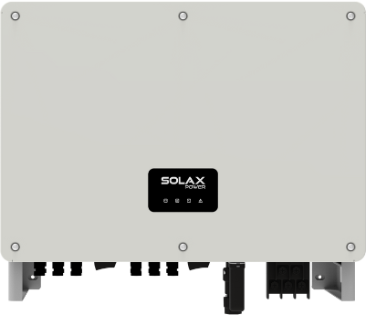
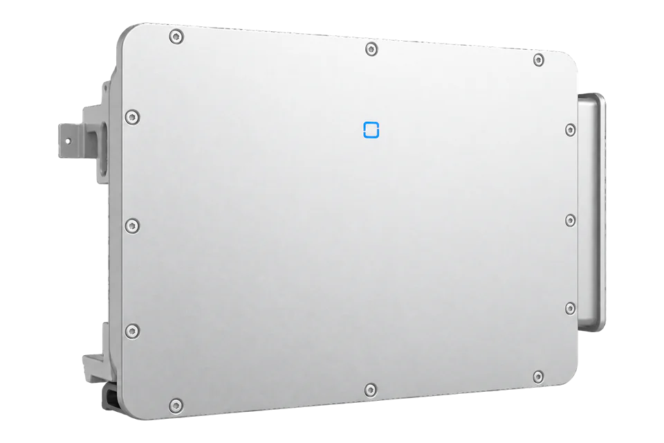
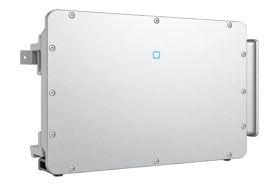
SolaX X3-MEGA G2 40/50/60 kW
Commercial grid-tied PV inverter
The X3-MGA-40K-G2, X3-MGA-50K-G2 and X3-MGA-60K-G2 are the 40, 50 and 60 kW 220/380 or 230/400 V models in SolaX's V3.3 sheet. The Version 13.0 manual separates the RS485 daisy-chain or data-collector pins from the meter pins and distinguishes DataHub and inverter-master export-control arrangements. An installation manual does not establish a third-party Edge register map or dispatch permission.
- RS485
- Modbus RTU
Commercial grid-tied PV inverter
Compatibility
Direct Edge integration not yet verified
The official manual documents RS485-1 inverter networking and an internal Modbus parallel arrangement. It also names a meter on separate RS485-2 pins. The retained sources do not include a firmware-matched external point map, permissions, polling limits or a validated Edge import; a Pocket LAN or DataHub accessory is not proof of direct Modbus TCP on the inverter.
Confirm the exact X3-MGA-40K/50K/60K-G2 nameplate, country code, firmware, installed SolaX meter and any DataHub or Pocket dongle. Obtain an authorised read-only interface contract for that topology. Leave export limiting, reactive power, RRCR/DRM, remote settings and VPP dispatch with the commissioned controls owner.
Models
| Models | Interface | Route into Edge |
|---|---|---|
| X3-MGA-40K-G2 | 40 kVA nominal, four MPPTs with two strings each, 220/380 or 230/400 V | Check exact country approval, firmware and the installed communication owner before any telemetry design. |
| X3-MGA-50K-G2 | 50 kVA nominal, five MPPTs with two strings each, 220/380 or 230/400 V | The meter and inverter-network RS485 ports serve different roles even when this model joins a multi-inverter plant. |
| X3-MGA-60K-G2 | 60 kVA nominal, six MPPTs with two strings each, 220/380 or 230/400 V | Verify current, protection and communications on its installed revision rather than assuming the 40 kW configuration. |
| X3-MGA-40K/50K/60K-G2(L) and 20/25/30/35K-G2-LV | Manual also discusses low-voltage and alternative regional variants | Excluded from this guide; do not transfer AC ratings, certification, country-code or terminal assumptions without their own nameplate and documents. |
Specifications
SolaX's V3.3 sheet covers exactly 40, 50 and 60 kW European-voltage models in this guide. It gives 4, 5 and 6 MPPTs respectively, 32 A maximum input current per MPPT, up to 150% recommended PV array power, IP66 and Type II AC/DC surge protection. Country code and current certificates determine whether a particular installation is approved.2
- Rated AC output
- 40, 50 or 60 kVA respectively; 220/380 or 230/400 V, three-phase2
- PV tracking
- Four, five or six MPPTs respectively; two strings per MPPT2
- RS485 inverter network
- RS485-1 pins 1/2 A/B in and 4/5 A/B out, or SolaX data collector3
- RS485 meter
- RS485-2 pins 7/8 A/B meter; site import/export requires correct grid-point installation3
- DataHub parallel topology
- Up to 60 inverters according to Version 13.0, with uniform firmware and under 200 m RS485 cabling3
- Enclosure
- IP66, smart air cooling; -25 to +60 °C stated operating range2
Interface
Documented measurements and integration boundaries for X3-MEGA G2 40/50/60 kW.
- The manual's communication connector assigns RS485-1 pins 1/2 as A/B in and 4/5 as A/B out for inverter networking or a data collector. RS485-2 pins 7/8 are the A/B meter connection. These roles are explicit; a meter port should not be described as a spare northbound monitoring port.
- SolaX documents a DataHub parallel design of up to 60 inverters and a separate Modbus inverter-master design of up to 10. The manual requires the same firmware on all parallel inverters and says the RS485 cable must be less than 200 m for the DataHub arrangement. These are plant-control design conditions, not an Edge fleet capacity claim.
- The Modbus parallel example gives slave addresses 2–11 and a meter address of 1 at 9600 baud. These addresses are example settings for SolaX's internal master/slave arrangement, not a published third-party register map or an instruction to change a commissioned plant.
- The datasheet advertises built-in export power control, remote setting and night-time reactive-power compensation. Those functions depend on a correctly installed grid-point meter, utility approval and a commissioned control owner. A protocol or DI/DO terminal does not authorise external writes.
- The manual names optional Pocket WiFi, LAN and 4G monitoring dongles, but its RS485 connector and dongle uplink are distinct. Verify which device actually offers a supported external read path, firmware and access policy before planning integration.
Assessment
The three named 220/380 or 230/400 V -G2 models, not the low-voltage or (L) variants discussed in the wider manual.
- InteroperabilityLimited
- The manual defines RS485 network and meter roles and an internal Modbus parallel mode, but no authorised external point map is retained.3
- AccuracyNot yet assessed
- External telemetry points, scaling, timestamps and grid-meter sign need a firmware-matched contract and live check.3
- SecurityNot yet assessed
- Read-only account, network and accessory access policy remain unverified for an installed system.3
- ReliabilityNot yet assessed
- Northbound polling and stale-data behaviour need the selected accessory and firmware documentation.3
- RuggednessSupported with conditions
- V3.3 lists IP66, smart air cooling and -25 to +60 °C; installation clearances and thermal derating still apply.2
- ScalabilityLimited
- SolaX describes 60 DataHub or 10 Modbus-master inverters by topology, not an Edge fleet guarantee.3
Setup
-
Identify the European-voltage model
Record the full X3-MGA-40K/50K/60K-G2 code, country code, firmware, grid approval and exact installed meter. The same manual also covers low-voltage variants that are outside this guide.
-
Map the existing plant control design
Trace whether the site uses a SolaX DataHub, Modbus inverter master or individual Pocket monitoring dongles. Do not add a second master or change addresses on an operating export-control bus.
-
Keep inverter and meter terminals distinct
Verify the installed connector before using RS485-1 pins 1/2 and 4/5 for the inverter network or RS485-2 pins 7/8 for the meter. Record termination, baud and existing addresses with the installer.
-
Get the authorised telemetry contract
Obtain the model, firmware and accessory-matched third-party point list and access rules. Confirm register offsets, function, decode, units, timestamps and polling limits. Compare one read with SolaX's own view before scaling.
-
Review flexibility and export separately
Verify the connection-point meter sign, CT orientation and controls owner. Keep export limits, reactive settings and utility dispatch on the approved controller until a separate safe control design is accepted.
Common questions
- Are the meter and data-collector connections the same RS485 port?
- No. The Version 13.0 terminal table assigns RS485-1 pins 1/2 and 4/5 to the inverter network or data collector, while RS485-2 pins 7/8 connect the meter. Preserve the commissioned wiring and verify the installed connector.3
- Does a Pocket LAN dongle provide direct Modbus TCP for Edge?
- The manual lists optional Pocket WiFi, LAN and 4G monitoring accessories, but it does not define a firmware-matched third-party TCP point service for this inverter. Obtain the exact accessory's authorised interface document before selecting a connection.3
- Can the inverter's remote setting be used for VPP dispatch?
- A datasheet capability does not grant third-party control rights. Export or reactive-power commands need the utility-approved grid-point measurement, site controller, permissions, fail-safe behaviour and separately reviewed commissioning plan.23
Related devices
Sources
- X3-MEGA G2 40/50/60 kW product page (opens in a new tab)
- X3-MEGA G2 40/50/60 kW datasheet, V3.3 (opens in a new tab) (PDF)
- X3-MEGA G2 Series User Manual, Version 13.0 (opens in a new tab) (PDF)
Product names and trademarks belong to their owners. Publication does not imply endorsement or a commercial relationship.