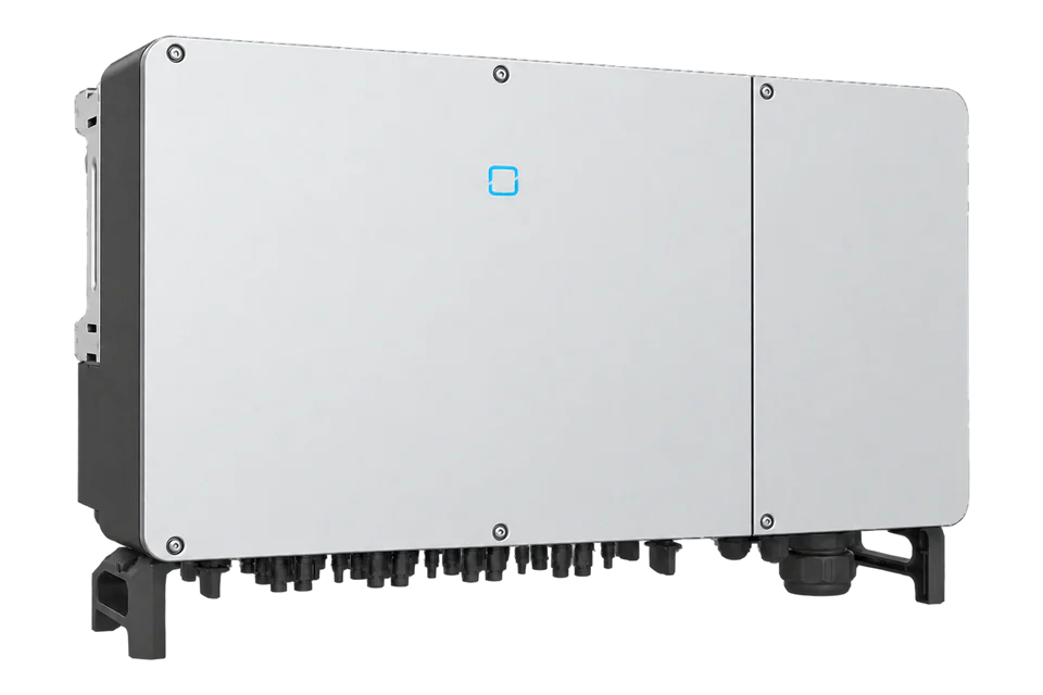
SolaX Power X3-ULTRA
Hybrid solar inverter
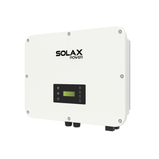
The X3-ULTRA combines three-phase PV, battery and backup circuits. SolaX documents a dedicated third-party RS-485 pin group and Pocket TCP monitoring. Its public protocol provides practical read-only starting points for grid voltage, frequency, battery state of charge and signed site power.
- Modbus RTU
- Modbus TCP
Hybrid solar inverter
Compatibility
Public monitoring map; Edge commissioning remains site-specific
SolaX documents Modbus RTU on the remote COM1 pair and Modbus TCP through supported Pocket modules. The retained OEM-authored V3.29 protocol explicitly names X3-ULTRA and supplies addresses and decoding. This guide has not established a tested Edge import.
Seven high-voltage X3-ULT variants in the V2.3 datasheet. Use the published map as a best-effort starting point and compare initial reads with the local display. Keep remote RS-485 separate from SolaX accessory wiring; TCP requires a compatible monitoring module. GLV and Belgian 25KW variants remain outside this electrical assessment.
Models
| Models | Interface | Route into Edge |
|---|---|---|
| X3-ULT-15K, 19.9K and 20K | Two MPPTs with two strings per MPPT; 19.9K is marked for Italy | Check the full nameplate and national grid-code setting; nominal rating does not establish export permission. |
| X3-ULT-15KP, 20KP, 25K and 30K | Three MPPTs with two strings per MPPT | The P suffix changes the PV input arrangement. Confirm the exact variant before selecting PV array monitoring expectations. |
| X3-ULT-10K-GLV, 15K-GLV and 25KW | Additional variants appear in manual version 16.0, outside the seven-column high-voltage datasheet | Do not extend this assessment to GLV or Belgian 25KW without its own regional electrical and protocol evidence. |
Specifications
SolaX lists seven 15–30 kW high-voltage variants in its V2.3 datasheet. The 15KP and 20KP units have a third MPPT; the corresponding non-P 15K and 20K have two. The 19.9K is identified for Italy.12
- Documented ratings
- 15, 19.9, 20, 25 and 30 kW; seven exact model codes2
- PV input
- Two or three MPPTs by variant; 1,000 V maximum PV input2
- Battery circuit
- 120–800 V lithium battery range; two battery ports, 60 A maximum combined charge or discharge current2
- Monitoring interfaces
- Modbus RTU on remote COM1 RS-485; Modbus TCP through a supported Pocket module, TCP 502456
- Enclosure
- IP66; -35 to +60 °C, with derating above 45 °C2
Interface
Documented measurements and integration boundaries for X3-ULTRA.
- PV, battery, inverter and meter values have different physical boundaries. Record which device originates each value before connecting a monitoring client.
- COM1 is an RS-485 connector, not Ethernet: remote pins 1/2 and 7/8 serve third-party communication; pins 3/4/5/6 are a separate bus for SolaX accessories.
- Start with FC04 grid voltage at 0x006A and frequency at 0x006D. Expand to battery state of charge, PV power and signed meter power after comparing readings with the local display.
Assessment
Seven high-voltage X3-ULT variants, public OEM-authored V3.29 reads and documented remote/Pocket monitoring paths. Control permission and installed Edge acceptance are separate.
- InteroperabilitySupported with conditions
- Public RTU/TCP registers and an explicitly permitted third-party COM1 pair provide a concrete monitoring starting point.456
- AccuracySupported with conditions
- The map specifies function, address, length, type, units and low-word-first meter decoding; local comparison establishes the installed measurement boundary.4
- SecuritySupported with conditions
- Pocket setup has local configuration access; segment its Modbus endpoint on the monitoring LAN. The protocol does not specify encrypted polling or read-only user roles.46
- ReliabilitySupported with conditions
- The protocol specifies a one-second minimum request interval and response timeout; use freshness timestamps and preserve the existing bus master.45
- RuggednessSupported with conditions
- IP66 and operating-temperature limits are published, with high-temperature derating.2
- ScalabilityLimited
- SolaX documents up to ten inverters with DataHub, but that is a vendor control topology and not a third-party polling capacity guarantee.1
Setup
-
Identify the exact inverter
Record the X3-ULT model code, country variant, serial number, installed firmware and any communication accessory. Use the P suffix and country designation to select the correct electrical limits.
-
Map the plant boundaries
Draw PV strings, both battery ports, BMS connections, grid and EPS circuits, meters, parallel links and any DataHub, EV charger or Adapter Box G2. Mark the origin of each proposed reading.
-
Wire the third-party RS-485 pair
Use COM1 remote pins 1/2 or 7/8 according to the manual pinout. SolaX explicitly permits third-party devices on this bus; keep accessory pins 3/4/5/6 separate. Re-crimp the RJ45 connector for the required pins rather than using a full Ethernet cable blindly. Follow the installed manual cable limit, retain one polling master per bus and record existing connections.
-
Choose RTU or Pocket TCP
Protocol V3.29 gives RTU defaults of address 1, 19200 baud, 8 data bits, no parity and 1 stop bit; match the actual inverter settings. TCP requires a SolaX monitoring module, not the COM1 connector: the protocol specifies port 502 and default unit 1. The OEM Pocket compatibility table lists X3-ULTRA ARM V4.04 and supported dongle versions. Enable the module locally, record its assigned IP and use the same protected LAN. Space requests by at least one second.
-
Read voltage and frequency
Use the retained OEM-authored V3.29 map, whose revision history ends in September 2023, as a best-effort starting point. FC04 input register 0x006A (decimal 106), quantity 1, gives R-phase grid voltage as U16 × 0.1 V. Request PDU: 04 00 6A 00 01. Synthetic response data 08 FC decodes to 230 V. Register 0x006D (109), quantity 1, gives frequency as U16 × 0.01 Hz: PDU 04 00 6D 00 01 and data 13 88 give 50 Hz. These are hexadecimal wire addresses; do not subtract one. Compare both with the local display before adding more readings.
-
Add battery, PV and site power
FC04 0x001C (28), quantity 1, is battery 1 state of charge, U16 in 1%; data 00 4B gives 75%. PV1/PV2 power at 0x000A/0x000B are U16 in W. Meter/CT power at 0x0046 (70), quantity 2, is signed 32-bit W with the low word first: PDU 04 00 46 00 02. Read each word as big-endian, then combine low + high × 65536 and apply two’s-complement sign. Data 30 39 00 00 gives +12345 W; CF C7 FF FF gives -12345 W. Positive indicates export and negative import. Check against the site meter, not inverter production alone. Inverter AC energy is separate: daily 0x0050 U16 × 0.1 kWh and total 0x0052/0x0053 U32, low word first, × 0.1 kWh.
-
Keep dispatch with its commissioned owner
Use these examples for monitoring. Battery dispatch, export limits, EPS transfer and grid settings remain with the commissioned control system. This guide supplies no operational write commands.
Common questions
- Can a VPP issue power commands using the advertised API or OpenADR support?
- The datasheet includes VPP protocol and API names with a note that some features are coming soon. Availability, roles, permissions and the contracted control path must be confirmed for the installed country variant and firmware. This guide publishes no command path.2
- Does the DataHub replace the site meter or prove Edge control?
- No. DataHub is SolaX's controller for its documented multi-inverter system. Point-of-connection metering and protection remain separately commissioned, and DataHub control does not establish an Edge write interface.1
- What changes between X3-ULT-20K and X3-ULT-20KP?
- The datasheet gives the 20K two MPPTs and the 20KP three, with two strings per MPPT. Check the full model code instead of selecting an array layout from the 20 kW rating alone.2
Related devices
Sources
- X3-ULTRA Series user manual, version 16.0 (opens in a new tab) (PDF)
- X3-ULTRA three-phase hybrid inverter datasheet, version 2.3 (opens in a new tab) (PDF)
- X3-ULTRA product page (opens in a new tab)
- SolaX X1/X3-IES and X3-ULTRA Modbus TCP/RTU protocol V3.29, public mirror (opens in a new tab) (PDF)
- Communication connectivity in different solutions: ULTRA (opens in a new tab)
- How to get device data by Modbus TCP (opens in a new tab)
Further reading
Product names and trademarks belong to their owners. Publication does not imply endorsement or a commercial relationship.