SATEC PM180
Power quality analyser
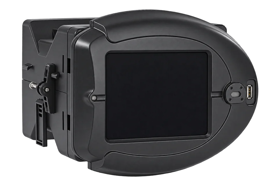
The PM180 is SATEC's modular power quality analyser for substations and large industrial sites: an IEC 61000-4-30 class A analyser, a class 0.2S energy meter and, with plug-in modules, a fault recorder, transient recorder and phasor measurement unit. It measures four voltage and four current channels through 5 A or 1 A CTs or SATEC HACS sensors. Every PM180 has a 10/100BaseT Ethernet port with a Modbus TCP server on port 502 and serial ports for Modbus RTU. SATEC numbers its registers in decimal and sends 32-bit integers low word first, with volts in 0.1 V and amps in 0.01 A when no PT is used.
Compatibility
Compatible with EpiSensor Edge over Modbus TCP or Modbus RTU
The PM180 is compatible with EpiSensor Edge over Modbus TCP on port 502 of its standard Ethernet port, and over Modbus RTU on an RS-485 serial port read through a ZMB-31 Modbus Interface or a Gateway serial port. SATEC publishes the register map with decimal addresses, data types, low-word-first word order, units and worked conversions.
PM180 with firmware V31.xx, using the PM180 Modbus reference guide BG0527 Rev. A11 with installation manual BG0521 Rev. A10 and operation manual BG0525 Rev. A7. Site check: read the energy decimal places at register 46258 and compare the first voltage read with the display. IEC 61850, IEC 60870-5, DNP3, IEEE C37.118 synchrophasors, power quality and fault log files are outside this guide. Read-only monitoring: no writes to setup, password, relay, reset or control registers.
Connect it with


The usual route: every PM180 has a 10/100BaseT Ethernet port on its CPU module
- Modbus
- Edge
- Platforms
When a wired network is not available and a free RS-485 port can be used
- Modbus
- Wireless
- Edge
- Platforms
When the Gateway sits in the same panel or cubicle as the analyser
- Modbus
- Edge
- Platforms
Models
| Models | Interface | Route into Edge |
|---|---|---|
| PM180 display options X, G, G-DIN, D, D-DIN | X: transducer with no display. G: RGM180 5.7 inch colour touchscreen. D: RDM180 three-line LED display. The -DIN versions come with a DIN-rail kit and a 3 m remote cable. | No effect on the Modbus map. A remote display normally takes COM3 (it can also use COM1 or COM2), and that port is then not free for Edge. |
| Current inputs 5, 1, CS1S, CS1H, HACS, FLEX | 5: 50 A input calibrated to 5 A, class 0.2S. 1: 10 A input calibrated to 1 A, class 0.2S. CS1S and CS1H: 100 A split-core HACS calibrated to 5 A, class 1. HACS: SATEC HACS sensors. FLEX: 3 V AC current clamps. | The register map is the same. The CT primary current at register 46213 scales current and power readings. |
| Power quality standard A, E, G (firmware V31.x4, V31.x5, V31.x7, V31.x8) | A: ANSI C12.20 accuracy with IEEE 1159 power quality. E: IEC 62053-22 with EN 50160. G: GOST 13109 or GOST 32144. Firmware V31.1x and V31.2x add IEC 61850 Ed1 or Ed2. | The real-time measurement registers are the same on every variant. Power quality statistics are log files, outside this guide. |
| Plug-in modules TXFX-180, IRIG-180, PMU, TRM-180, DFR, DI16, RLY8, 4AIO, BACDC-180 | Up to three modules: TXFX-180 adds a redundant copper or fibre Ethernet port and a second RS-422/485 port; IRIG-180 adds IRIG-B and a second RS-422/485 port; PMU, transient and fault recorders; digital inputs, relays and analog I/O; a backup auxiliary supply. | TXFX-180 and IRIG-180 give an extra Modbus port. Relay outputs and setpoints are control functions; keep them out of a monitoring poll. |
Specifications
The PM180 combines a class 0.2S multifunction energy meter, an IEC 61000-4-30 class A edition 3 power quality analyser with harmonics and interharmonics to the 63rd order, waveform and data recorders, and a programmable controller with 64 setpoints in one modular case. Three plug-in slots take communication, I/O, transient recorder, fault recorder, phasor measurement or backup power modules.24
- Inputs
- Four voltage channels, nominal 57/100, 277/480 or 400/690 V AC, up to 828 V AC direct or through PTs; a 120 V input option U. Four current channels through 5 A or 1 A CTs (continuous overload 10 × In), SATEC HACS sensors or 3 V AC clamps.24
- Accuracy
- Active energy class 0.2S to IEC 62053-22 and class 0.2 to ANSI C12.20; reactive energy class 0.5S. Power quality to IEC 61000-4-30 class A, edition 3.4
- Ethernet
- Transformer-isolated 10/100BaseT on RJ45, 4 kV AC isolation. Modbus TCP on port 502, DNP3/TCP on port 20000, IEC 60870-5-104 on port 2404 and IEC 61850; five simultaneous connections, two of them Modbus TCP.34
- Serial ports
- COM1 RS-232 on the CPU module, RS-485 on N3 versions; COM2 RS-422/485 on a communication module; COM3 RS-485 for the remote display; COM4 infrared. Up to 115.2 kbit/s, Modbus RTU, Modbus ASCII or DNP3. Factory settings: Modbus RTU, address 1, 19,200 bit/s, 8 data bits, no parity.23
- USB
- Isolated USB 1.1 port with Modbus RTU, for local configuration with PAS.4
- Power supply
- Standard AC/DC supply 50 to 290 V AC 50/60 Hz or 90 to 290 V DC, 10 W maximum. Optional auxiliary supply module, 50 to 290 V AC or 40 to 290 V DC, or 9.6 to 35 V DC.4
- Construction
- DIN-rail, panel or 19 inch rack mounting; 220 × 152 × 210 mm; 2.5 kg. Display panel IP54, instrument IP30.4
- Environment
- Operating -25 to +60 °C; storage -30 to +85 °C.4
Interface
Documented measurements and integration boundaries for PM180.
- Addresses are decimal and go on the wire as printed: register 13952 is sent as 36 80. A client that wants Modicon numbers adds 40001, or 400001 above 9999, so 13952 becomes 413953. FC03 and FC04 return the same registers, at most 120 registers per request.
- 32-bit values are two registers, low-order word first, with the low word at an even address. The PM180 has no floating-point option: 32-bit values are always UINT32 or INT32, with fractional values pre-multiplied by 10, 100 or 1000.
- Units are fixed by the PT ratio. With a PT ratio of 1: volts in 0.1 V and power in 1 W, var or VA. With a PT ratio above 1: volts in 1 V and power in 1 kW, kvar or kVA. Amps are always 0.01 A.
- 1-second phase voltages V1, V2 and V3 at 13952, 13954 and 13956: UINT32. They are line-to-neutral in 4LN3, 4LL3, 3LN3, 3LL3, 3BLN3 and 3BLL3 wiring and line-to-line otherwise. V12, V23 and V31 at 14012, 14014 and 14016.
- Currents I1, I2 and I3 at 13958, 13960 and 13962 and I4 at 14464: UINT32 in 0.01 A. Neutral current at 14466. Frequency at 14468 (UINT32, 0.01 Hz), to three decimals at 14484 and to four at 14490.
- Per-phase kW at 13964, 13966 and 13968 and kvar at 13970, 13972 and 13974: INT32. kVA at 13976 to 13980: UINT32. Power factor L1 to L3 at 13982, 13984 and 13986: INT32, × 0.001.
- Totals: kW at 14336 and kvar at 14338 (INT32), kVA at 14340 (UINT32), power factor at 14342 (INT32, × 0.001), kW import at 14348 and kW export at 14350 (UINT32), average L-N voltage at 14356 and average current at 14360. 10-minute total kW, kvar, kVA and power factor at 14272 to 14278.
- Energy: kWh import at 14720, kWh export at 14722, kWh net at 14724 (INT32), kvarh import at 14728, kvarh export at 14730, kVAh total at 14736, kVAh import at 14742 and kVAh export at 14744. UINT32, 0 to 999,999,999. The unit is set by the number of energy decimal places at register 46258: 0 (the default) is 1 kWh, up to 3 for 0.001 kWh.
- Per-phase kWh import L1 to L3 at 14848, 14850 and 14852 and kWh export L1 to L3 at 14866, 14868 and 14870. kvarh Q1 to Q4 at 14756, 14758, 14760 and 14762.
- Voltage THD V1 to V3 at 13988, 13990 and 13992 and current THD I1 to I3 at 13994, 13996 and 13998: UINT32, 0.1 %, 3-second values. Internal temperature at 14482 (INT32, 0.1 °C).
- Registers 256 to 308 are a 16-bit basic set scaled 0 to 9999 between low and high engineering scales. Prefer the 32-bit registers, which need no scale arithmetic.
- Identity: serial number at 46080 (UINT32), model ID at 46082 (18000), model name at 46084 to 46091 ("PM180") and firmware version at 46100 (3101 to 3199). Wiring mode at 46208, PT ratio at 46209 (× 0.1) and CT primary current at 46213.
- Setup, the authorisation register (44378), user login (44442 onward), relay outputs, setpoints, reset and clear registers, and the assignable map (0 to 239) accept writes, as does function 22. Keep them out of a monitoring poll.
Assessment
PM180 with firmware V31.xx, using the PM180 Modbus reference guide BG0527 Rev. A11 with installation manual BG0521 Rev. A10 and operation manual BG0525 Rev. A7. Site check: read the energy decimal places at register 46258 and compare the first voltage read with the display. IEC 61850, IEC 60870-5, DNP3, IEEE C37.118 synchrophasors, power quality and fault log files are outside this guide. Read-only monitoring: no writes to setup, password, relay, reset or control registers.
- InteroperabilityWell supported
- SATEC documents Modbus TCP on port 502 and Modbus RTU or ASCII on the serial ports, the supported function codes, the 120-register limit and exception responses, decimal addresses with the Modicon offsets, data types, low-word-first word order with worked examples, and the unit table.13
- AccuracyWell supported
- Class 0.2S active energy, IEC 61000-4-30 class A power quality, four voltage and four current channels, per-phase and total power, four-quadrant and per-phase energy. Units follow one documented rule from the PT ratio, and the energy unit is one register to read.14
- SecuritySupported with conditions
- An 8-digit password with three levels protects setups, counters and logs, and devices with enhanced security add named user logins for remote access. Password protection ships disabled, and Modbus TCP carries no encryption, so enable it and keep the analyser on a trusted network.13
- ReliabilityWell supported
- The datasheet lists IEC 61000-4-2 to 4-12 and IEC 60255-22 immunity with levels, including 6 kV surge and 4 kV fast transients, and an optional redundant auxiliary supply for recording through dips and interruptions. The guide documents exception codes and per-socket file pointers, and idle TCP sockets close after 5 minutes. Treat failed reads as missing data.134
- RuggednessSupported with conditions
- Rated -25 to +60 °C operating, with IEC 60255-21 vibration, shock and seismic tests, an IP54 display panel and an IP30 instrument body. Mounting inside a cubicle or rack.4
- ScalabilitySupported with conditions
- Modbus addresses 1 to 247 on the serial ports, any unit identifier over TCP, up to 120 registers per request and 120 user-assignable registers. Only two Modbus TCP sockets are available, so plan which clients poll the analyser.14
- LifecycleSupported with conditions
- Firmware is stored in flash and can be upgraded through a serial, USB or Ethernet port, with the version readable at 46100. The reference guide carries a revision history from 2012 to September 2024 and the datasheet is dated July 2024. The warranty is 24 months from dispatch, capped at 36 months from production. No support period or end-of-sale date is stated.124
Setup
Read V1 voltage from decimal register 13952
PM180 Modbus reference guide BG0527 Rev. A11, section 3.4, lists the 1-second V1 voltage at registers 13952 and 13953 as UINT32 with unit U1, chapter 4 sets U1 to 0.1 V when the PT ratio is 1, and section 2.6.2 sends 32-bit values low word first. This example is a 230/400 V supply in 4LN3 wiring with no PTs. Use the map as the starting point and compare the result with the display.
- Request
- 01 03 36 80 00 02 CA 6B: Modbus address 1, FC03, register 13952 (0x3680), two registers, RTU CRC. Over Modbus TCP the same function, address and length go to port 502 with any unit identifier. To check the energy unit first, 01 03 B4 B2 00 01 03 DD reads register 46258.
- Address convention
- The guide's register numbers are the zero-based PDU addresses in decimal: send 13952, which is 0x3680. A client that numbers holding registers from one shows it as 413953. Do not send 13953 or 413953 as the address.
- Synthetic response
- 01 03 04 08 FC 00 00 38 63: four data bytes, low word 08 FC first, then high word 00 00.
- Decode
- UINT32 with the low word first: 0 × 65536 + 0x08FC = 2300. With a PT ratio of 1, U1 is 0.1 V, so V1 is 230.0 V line-to-neutral. Behind PTs the same register counts whole volts in primary units. A client that takes the high word first reads 0x08FC0000 = 150,732,800.
- Acceptance
- Keep the point when it agrees with V1 on the display or in PAS at the same time. If it does not, check the PT ratio at 46209, the word order and the wiring mode at 46208 before adding more points.
Acceptance: The response bytes are a synthetic decoder check, not a captured device reply. A real reply must agree with the display before current, power and energy points are enabled.
-
Identify the analyser
Read the order code and the device information page: display version, current inputs, power quality standard and the modules in the three slots. Record the wiring mode, PT ratio and CT primary current from the basic setup.
-
Find the port
For Modbus TCP, note the IP address from the network setup in PAS or the display. For Modbus RTU, use a free RS-485 port: serial ports are factory set to Modbus RTU, address 1, 19,200 bit/s and 8 data bits with no parity. Enter the same values in the Edge client.
-
Connect
Connect the Ethernet port to the site network, or wire the RS-485 pair and terminate both ends of the bus. Leave COM3 to the remote display if one is fitted.
-
Make two reads
Read register 46258, one register, to learn the energy decimal places. Then read V1 at 13952 for two registers and decode it low word first, as in the worked read below. Compare the result with the V1 voltage on the display or in PAS.
-
Add the points you need
Add currents, powers and the energy counters from 14720, scaled by the PT ratio rule and the energy decimal places. Keep reads to 120 registers per request and keep writes out of the polling configuration.
Common questions
- Why does voltage read 2300 and not 230?
- With a PT ratio of 1 the PM180 sends voltage in 0.1 V and power in watts, so 2300 is 230.0 V. When PTs are configured (PT ratio above 1) the same registers carry whole volts and kilowatts. Current is always in 0.01 A. Read the PT ratio at register 46209 and set the scale in Edge to match.1
- How do I scale the PM180 energy registers?
- The energy registers from 14720 count in a unit set by the number of energy decimal places at register 46258: 0, the default, is whole kWh, and 1 to 3 give 0.1, 0.01 or 0.001 kWh. Read 46258 once and compare the kWh import counter with the display.1
- Does the PM180 send floating-point values?
- No. The guide lists three formats: 16-bit scaled integers, 32-bit integers and 32-bit modulo-10000 energy counters. 32-bit values are signed or unsigned integers sent low word first, with fractional values pre-multiplied, such as 50.01 Hz sent as 5001.1
- Which port should Edge use?
- The standard Ethernet port, with Modbus TCP on port 502. It allows five simultaneous connections, two of them Modbus TCP, alongside DNP3, IEC 60870-5-104 and IEC 61850 sessions for the SCADA. Use an RS-485 port only when the network cannot reach the analyser.34
- Can Modbus writes change the analyser's settings?
- Yes. Setup, reset, relay and control registers are writable. The PM180 ships with password protection disabled; when it is enabled, the 8-digit password goes to the authorisation register 44378 before a write, or devices with enhanced security require a user login, and the PM180 answers unauthorised writes with exception code 01. A monitoring configuration should read with FC03 only.13
Related devices

Sources
- expertmeter High Performance Analyzer PM180 Modbus communications protocol reference guide, BG0527 Rev. A11 (September 2024) (opens in a new tab) (PDF)
- PM180 Series Substation Automation Unit installation manual, BG0521 Rev. A10 (opens in a new tab) (PDF)
- PM180 Series Substation Automation Unit operation manual, BG0525 Rev. A7 (opens in a new tab) (PDF)
- PM180 datasheet, July 2024, with options and order string (opens in a new tab) (PDF)
Further reading
- ApplicationTransformer and distribution board monitoring
- ToolModbus register address translator
- ToolModbus data decoder
- GuideModbus TCP vs Modbus RTU
- GuideHigh-accuracy electricity metering
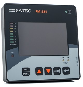
- GuideSATEC PM135: a SATEC panel meter with the same register layout
- ToolRS-485 termination and bias
- ManufacturerSATEC devices
- ProtocolModbus devices and register maps
- CategoryEnergy meters
Product names and trademarks belong to their owners. Publication does not imply endorsement or a commercial relationship.