SATEC BFM II
Multi-circuit power meter
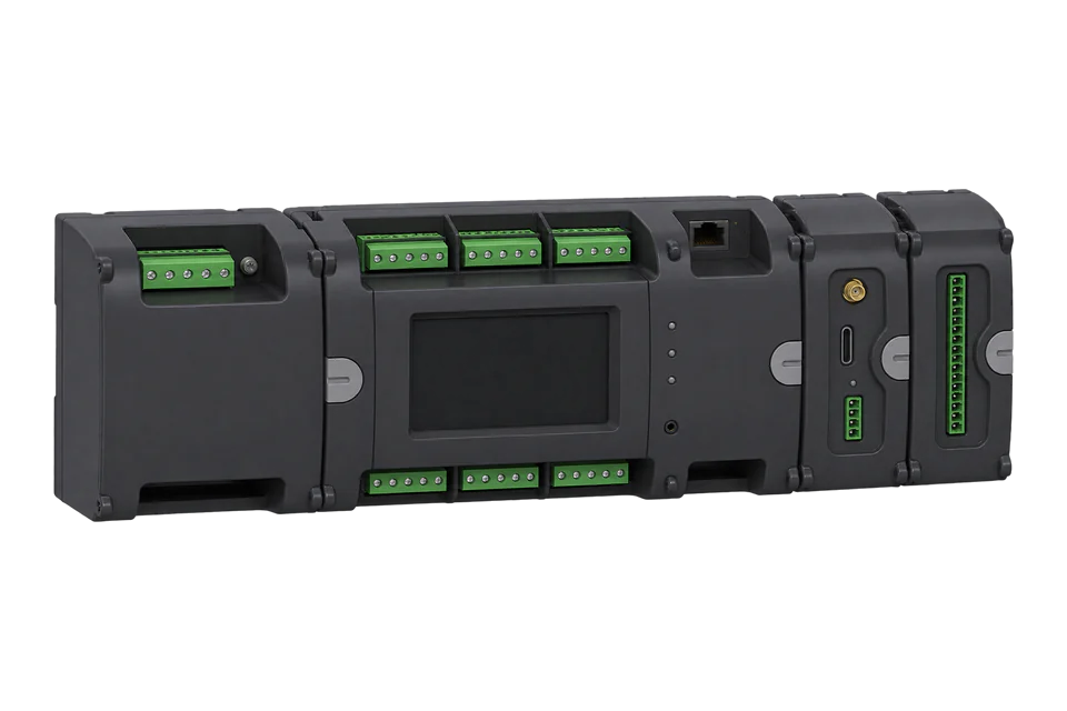
The BFM II is SATEC's DIN-rail branch feeder monitor: one voltage module and up to 54 current channels, grouped into submeters that each meter a three-phase or single-phase circuit. It measures through SATEC's High Accuracy Current Sensors only, never 1 A or 5 A CT secondaries. Every BFM II has an RS-485 port and an Ethernet port, both with Modbus. Each submeter answers at its own Modbus address, counted up from the device's base address, and exposes the same register map: decimal addresses, 32-bit integers sent low word first, and energy in 0.1 kWh.
Compatibility
Compatible with EpiSensor Edge over Modbus TCP or Modbus RTU
The BFM II is compatible with EpiSensor Edge over Modbus TCP on port 502 of its standard Ethernet port, and over Modbus RTU on its COM1 RS-485 port read through a ZMB-31 Modbus Interface or a Gateway serial port. SATEC publishes the register map with submeter addressing, decimal addresses, data types, low-word-first word order and units.
BFM II EM and DFR versions, using the BFM II Modbus reference guide BG0589 Rev. A12 with operation and installation manual BG0588 Rev. A12. Each submeter is a separate Modbus address from the base address. Site check: read the channel assignments and compare one submeter's current and kWh with the display before polling the rest. DNP3, IEC 60870-5, BACnet, fault records and the DFR waveform files are outside this guide. Read-only monitoring: no writes to setup, password, relay or reset registers.
Connect it with


The usual route: every BFM II has a 10/100BaseT Ethernet port on its main module
- Modbus
- Edge
- Platforms
For a monitor in a distribution board where a wireless link avoids running a data cable back to the Gateway
- Modbus
- Wireless
- Edge
- Platforms
When the Gateway sits near the monitor, or several monitors share one wired RS-485 bus
- Modbus
- Edge
- Platforms
Models
| Models | Interface | Route into Edge |
|---|---|---|
| BFM II EM | Multi-circuit revenue meter: up to 54 current channels as 18 three-phase or 54 single-phase submeters, harmonics to the 25th order, time-of-use registers; COM1 RS-485, Ethernet and USB standard | Read each submeter at its own Modbus address over Modbus TCP or COM1. |
| BFM II DFR | Adds a digital fault recorder with waveform capture on 36 current and 4 voltage channels at up to 40 × In; limited to 12 three-phase current channels | Same read path for the 1-second values and energy. Fault records and waveforms are log files, outside this guide. |
| Current input options HACS, RS5, FLEX (CIM modules C6H, C6R, C6F, C18H, C18R, C18F) | HACS: 40 mA input for SATEC HACS sensors of 100 to 3000 A. RS5: 5 A split-core HACS clipped onto existing CT secondaries. FLEX: 3 V AC current sensors. Each current input module carries one type. | The register map is the same. SATEC warns that wiring standard 1 A or 5 A CT outputs straight to the inputs destroys them. |
| VIM50Hz, VIM60Hz voltage input module | A second set of three-phase voltage inputs for a parallel supply; each current channel is assigned to one of the two voltage sets; limits the monitor to 36 current channels | No change to the map. Check which voltage set each submeter uses before comparing readings. |
| T4G-BFM II, DI9, DI18, RLY9, AI modules | 4G modem with Modbus TCP; digital inputs, relay outputs and analog inputs | Use the wired Ethernet or RS-485 port for a local Edge read. Relay outputs are control functions; keep them out of a monitoring poll. |
Specifications
The BFM II is a modular DIN-rail meter for many circuits in one board: a main module with the voltage inputs, communication ports and optional 3.5 inch touch display, plus current input modules that carry 6 or 18 channels each. It measures true RMS volts, amps, power, power factor, neutral current and frequency per submeter, four-quadrant energy, time-of-use registers and harmonics to the 25th order.23
- Circuits
- Up to 54 current channels: 18 three-phase or 54 single-phase submeters, plus totalisation submeters 55 to 60. With the second voltage module, up to 36 channels.23
- Voltage inputs
- Nominal 277/480 V AC, ±15 %; direct measurement 0 to 561 V AC; installation category III; 4LN3 wye or 4LL3 delta wiring.13
- Current inputs
- SATEC HACS sensors only, solid or split core, 5 A to 3000 A primary: 40 mA inputs for HACS, the RS5 input for 5 A split-core HACS, or 3 V AC FLEX sensors.3
- Accuracy
- Active energy class 0.5S to IEC 62053-22 with solid-core HACS, class 1 with split-core HACS; ANSI C12.20 class 0.5 %. Voltage 0.1 % and current 0.2 % of reading.3
- Serial ports
- COM1 optically isolated two-wire RS-485 (4 kV AC), three removable terminals, up to 115,200 bit/s, Modbus RTU, Modbus ASCII or DNP3; optional COM2 RS-422/485; COM3 for the display. Factory settings: Modbus RTU, address 1, 19,200 bit/s, 8 data bits, no parity.23
- Ethernet
- Transformer-isolated 10/100BaseT on RJ45, standard. Modbus TCP on port 502 and DNP3/TCP on port 20000, five simultaneous connections, SNTP time synchronisation. Factory IP 192.168.0.203, mask 255.255.255.0, gateway 192.168.0.1.23
- Power supply
- Self-energised from the voltage inputs, 70 to 561 V AC 50/60 Hz from any phase, or the auxiliary module at 50 to 290 V AC or 40 to 290 V DC (90 V DC minimum above 60 °C).3
- Construction
- DIN-rail mounting; 278 mm wide for 18 channels, 554 mm for 54 channels; 128 mm high and 72.5 mm deep; 1.6 kg for 36 channels; IP50.3
- Environment
- Operating -30 to +70 °C, with full accuracy from -25 to +60 °C; storage -40 to +85 °C; 0 to 95 % humidity non-condensing; altitude up to 2000 m.3
Interface
Documented measurements and integration boundaries for BFM II.
- Submeter addressing: the device address set in the communication setup is the base address N. Submeter 1 answers at N, submeter 2 at N + 1 and so on; submeters 55 to 60 are totalisation meters. A submeter is active once a current input is assigned to it. Setup registers are shared, measurement and energy registers are per submeter.
- Addresses are decimal and go on the wire as printed: register 14720 is sent as 39 80. A client that wants Modicon numbers adds 40001, or 400001 above 9999, so 14720 becomes 414721. FC03 and FC04 return the same registers.
- 32-bit values are two registers, low-order word first, with the low word at an even address. The BFM II has no floating-point option: 32-bit values are UINT32 or INT32, with fractional values pre-multiplied, such as frequency in 0.01 Hz.
- Units are fixed by the PT ratio. With a PT ratio of 1: volts in 0.1 V and power in 0.001 kW, kvar or kVA. With a PT ratio above 1: volts in 1 V and power in 1 kW. Amps are always 0.01 A.
- 1-second voltages V1, V2 and V3 at 13952, 13954 and 13956 and V12, V23 and V31 at 14012, 14014 and 14016: UINT32.
- Submeter currents I1, I2 and I3 at 13958, 13960 and 13962: UINT32 in 0.01 A. Neutral current at 14466 and frequency at 14468 (UINT32, 0.01 Hz).
- Submeter per-phase kW at 13964, 13966 and 13968 and kvar at 13970, 13972 and 13974: INT32. kVA at 13976 to 13980: UINT32. Power factor L1 to L3 at 13982, 13984 and 13986: INT32, × 0.001.
- Submeter totals: kW at 14336 and kvar at 14338 (INT32), kVA at 14340 (UINT32), power factor at 14342 (INT32, × 0.001), kW import at 14348 and kW export at 14350 (UINT32).
- Submeter energy: kWh import at 14720, kWh export at 14722, kvarh import at 14728, kvarh export at 14730 and kVAh total at 14736. UINT32, 0 to 999,999,999, in 0.1 kWh, kvarh or kVAh per the register table. Billing summary registers 1 to 8 at 14784 to 14799, also 0.1 kWh.
- The device options also hold the number of decimal places for energy registers at 46271 (0 to 4, default 4). Read it, and compare one kWh counter with the display once, before trusting the 0.1 kWh scale on a site.
- Channel assignments start at 46928, four registers per submeter: CT primary current, then the L1, L2 and L3 current input numbers (0 not assigned, 1 to 54 for I1 to I54). Submeter names (16 characters) start at 47400, eight registers each.
- Identity: serial number at 46080 (UINT32), model ID at 46082 (15400), model name at 46084 to 46091 ("BFM II") and firmware version at 46100. Wiring mode at 46208 (1 4LN3 wye, 2 4LL3 delta).
- Setup, the authorisation register (44378), relay outputs, reset and clear registers and the assignable map (0 to 239) accept writes, and setup writes on any submeter address change every submeter. Keep them out of a monitoring poll.
Assessment
BFM II EM and DFR versions, using the BFM II Modbus reference guide BG0589 Rev. A12 with operation and installation manual BG0588 Rev. A12. Each submeter is a separate Modbus address from the base address. Site check: read the channel assignments and compare one submeter's current and kWh with the display before polling the rest. DNP3, IEC 60870-5, BACnet, fault records and the DFR waveform files are outside this guide. Read-only monitoring: no writes to setup, password, relay or reset registers.
- InteroperabilityWell supported
- SATEC documents Modbus RTU, ASCII and TCP, submeter addressing with a worked example, function codes and exception responses, decimal addresses with the Modicon offsets, data types, low-word-first word order and the unit table.12
- AccuracySupported with conditions
- Class 0.5S active energy per circuit with solid-core HACS, class 1 with split-core HACS, 1-second values and four-quadrant energy for up to 54 channels. The register table gives energy in 0.1 kWh while a decimal-places setting also exists, and the two SATEC documents disagree on the factory submeter count, so confirm one submeter against the display.123
- SecuritySupported with conditions
- Three password levels protect setups, counters and logs, the security setup register reads password protection as always on, and the passwords ship preset to 9. Modbus carries no encryption, so change the passwords and keep the monitor on a trusted network.12
- ReliabilitySupported with conditions
- The datasheet lists IEC 61000-4-2 to 4-12 immunity with levels, including 6 kV surge on the measuring circuits, and ANSI C12.1 surge and ring-wave tests. A self-energised monitor depends on the measured voltage; the auxiliary supply module removes that dependency. Treat failed reads as missing data.13
- RuggednessSupported with conditions
- Rated -30 to +70 °C operating and up to 2000 m, IP50, with IEC 62052-11 vibration and shock tests. DIN-rail mounting inside a distribution board.3
- ScalabilitySupported with conditions
- One monitor covers up to 54 channels with one wiring job, and each submeter shares the same point list. Every submeter takes a Modbus address, so a bus or TCP client fills its address range quickly, and setup is shared across all submeters.123
- LifecycleSupported with conditions
- Firmware can be upgraded in the field through any communication port and its version is readable at 46100. The reference guide carries a revision history from 2015 to May 2024 and the datasheet is dated February 2025. The warranty is 24 months from dispatch, capped at 36 months from production, and applies only with SATEC HACS sensors. No support period or end-of-sale date is stated.123
Setup
Read submeter 3 kWh import from decimal register 14720
BFM II Modbus reference guide BG0589 Rev. A12, section 2.6, gives submeter 3 the base address plus 2, section 3.4 lists kWh import at registers 14720 and 14721 as UINT32 in 0.1 kWh, and section 2.7.2 sends 32-bit values low word first. This example is a monitor at the factory base address 1. Use the map as the starting point and compare the result with the display.
- Request
- 03 03 39 80 00 02 C8 9D: Modbus address 3 (submeter 3), FC03, register 14720 (0x3980), two registers, RTU CRC. Over Modbus TCP the same function, address and length go to port 502 with unit identifier 3. The same submeter's I1 current is 03 03 36 86 00 02 2B 88, register 13958.
- Address convention
- The guide's register numbers are the zero-based PDU addresses in decimal: send 14720, which is 0x3980. A client that numbers holding registers from one shows it as 414721. Do not send 14721 or 414721 as the address.
- Synthetic response
- 03 03 04 E2 40 00 01 2F 9F: four data bytes, low word E2 40 first, then high word 00 01.
- Decode
- UINT32 with the low word first: 1 × 65536 + 0xE240 (57920) = 123456. At 0.1 kWh per count, submeter 3 has imported 12,345.6 kWh. A client that takes the high word first reads 0xE2400001 = 3,795,845,121.
- Acceptance
- Keep the point when it agrees with submeter 3's kWh import on the display. If it reads ten times too large or too small, check the energy decimal places at 46271. If it belongs to another circuit, check the base address and the channel assignments from 46928.
Acceptance: The response bytes are a synthetic decoder check, not a captured device reply. A real reply must agree with the display before the other submeters are added.
-
Map the submeters
In PAS or on the display, read the channel assignments: which current inputs belong to each submeter and its CT primary rating, and any totalisation submeters. Note the base address; submeter k answers at the base address plus k minus 1.
-
Read the port settings
COM1 is factory set to Modbus RTU, address 1, 19,200 bit/s and 8 data bits with no parity. The Ethernet port's factory IP address is 192.168.0.203. Enter the same values in the Edge client and leave the monitor's settings as they are.
-
Wire the connection
For Modbus TCP, connect the RJ45 port to the site network. For RS-485, wire the COM1 terminals, terminate both ends of the bus and keep every other device's address outside the monitor's submeter range.
-
Check one submeter
At the first submeter's address, read I1 at 13958 and kWh import at 14720, two registers each, and decode them low word first, as in the worked read below. Compare both with the same submeter on the display.
-
Add the other submeters
Add one Edge device per submeter address with the same point list. Keep setup, relay and reset registers out of the polling configuration: a setup write on any address changes the whole monitor.
Common questions
- How does one BFM II appear on a Modbus network?
- As a block of consecutive Modbus addresses, one per active submeter, starting at the device's base address. Submeter 1 is at the base address, submeter 2 at the next address, and so on. On a shared RS-485 bus, give each monitor a base address whose block does not overlap another device.12
- How many submeters does a new BFM II have?
- The two SATEC documents differ. The operation manual says the factory setup is six three-phase submeters at addresses 1 to 6; the Modbus guide says 18 three-phase submeters at addresses 1 to 18. Read the channel assignments from register 46928 or in PAS rather than assuming either.12
- Can I connect existing 5 A CTs to a BFM II?
- Not directly. The BFM II takes SATEC HACS sensors only, and SATEC warns that wiring 1 A or 5 A CT outputs to the inputs destroys them. For existing CTs, order the RS5 version and clip a 5 A split-core HACS onto each CT secondary.3
- Which unit identifier does Edge use over Modbus TCP?
- The submeter's address. The manual says the Ethernet port answers any device address, and it also has PAS select a submeter address over the same connection, so set the unit identifier to the submeter's address and confirm with one submeter's current before adding the rest.12
- Why does a 32-bit value read as billions?
- The client is taking the high word first. The BFM II sends the low-order word in the first register and the high-order word in the second. Swap the two registers in the Edge point definition.1
- Can Modbus writes change the monitor's settings?
- Yes. Setup, relay and reset registers are writable, and a setup write on any submeter address changes the whole monitor. The BFM II ships with all three passwords preset to 9; with protection enabled, the password goes to the authorisation register 44378 before a write, or the monitor answers with exception code 01. A monitoring configuration should read with FC03 only.12
Related devices

Sources
- Branch Feeder Monitor BFM-II MODBUS communications protocol reference guide, BG0589 Rev. A12 (May 2024) (opens in a new tab) (PDF)
- Branch Feeder Monitor BFM II EM and DFR operation and installation manual, BG0588 Rev. A12 (opens in a new tab) (PDF)
- BFM II datasheet, February 2025, with options and order string (opens in a new tab) (PDF)
Further reading
- ApplicationTenant submetering and cost allocation
- ToolModbus register address translator
- ToolModbus data decoder
- GuideElectricity submetering in commercial buildings
- GuideModbus TCP vs Modbus RTU
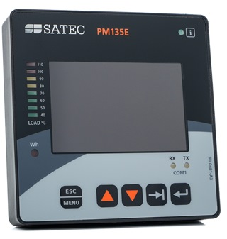
- GuideSATEC PM135: a single-circuit SATEC meter with the same register layout
- ToolRS-485 termination and bias
- ManufacturerSATEC devices
- ProtocolModbus devices and register maps
- CategoryEnergy meters
Product names and trademarks belong to their owners. Publication does not imply endorsement or a commercial relationship.