Deye BOS-G
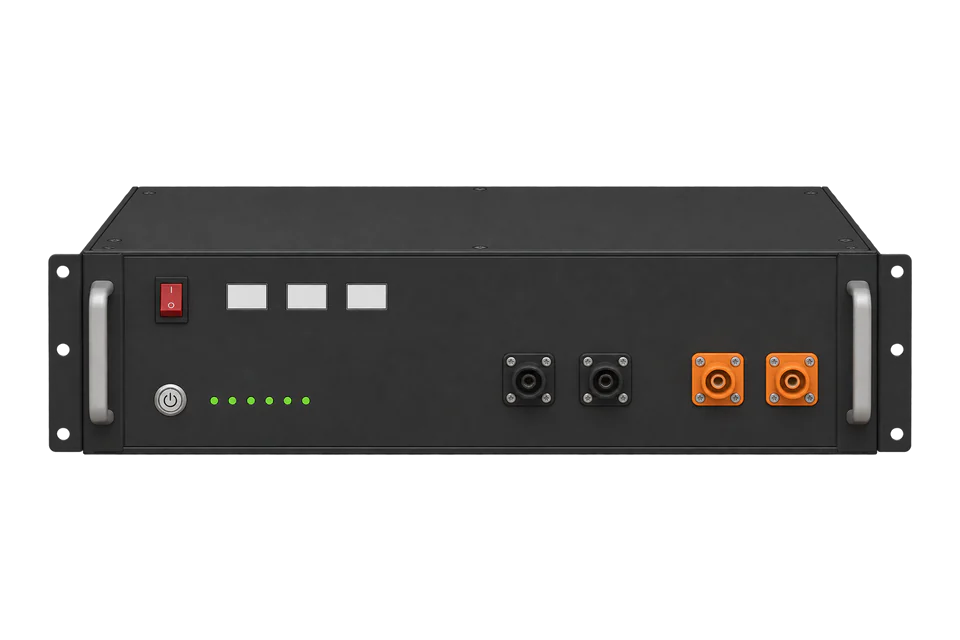
High-voltage battery energy storage system
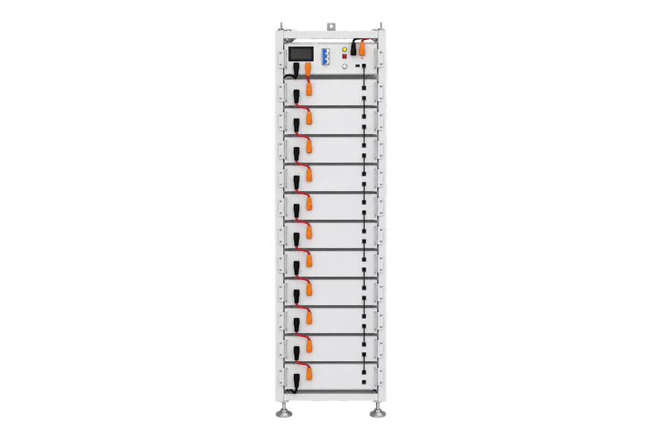
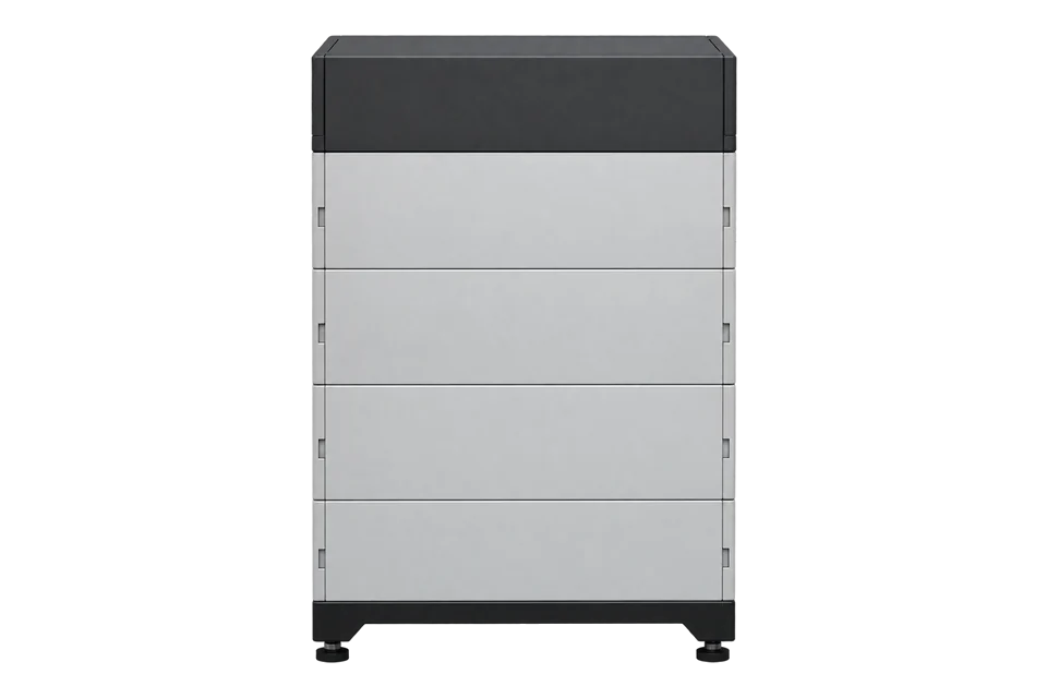
BOS-G racks stack 3 to 12 BOS-GM5.1 modules of 5.12 kWh under one HVB750V/100A control box, from 15.36 to 61.44 kWh. The control box sends battery information to the inverter over CAN or RS485. Edge reads each rack’s state of charge, voltage and current through the Deye SUN-29.9-50K-SG01HP3 inverter’s RS485 port with Deye’s public three-phase storage Modbus protocol.
Compatibility
Compatible with EpiSensor Edge through the Deye SUN-SG01HP3 inverter that manages the battery
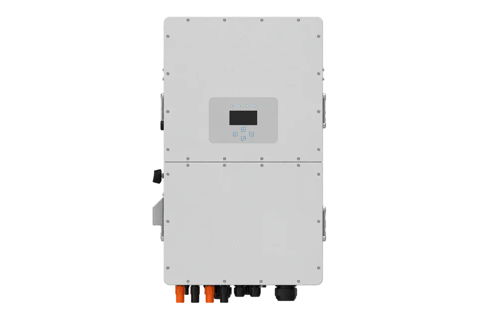
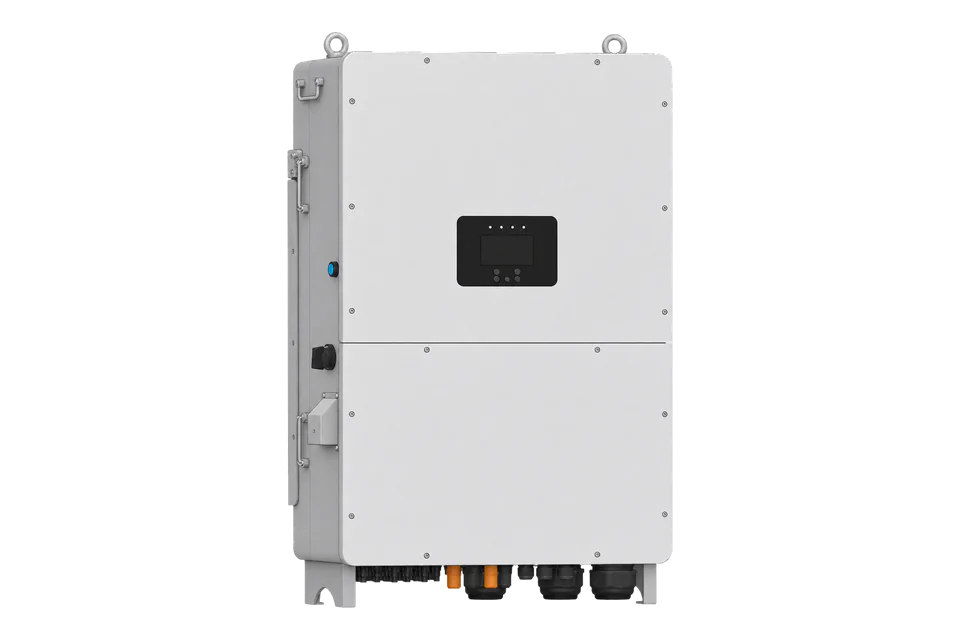
Deye pairs BOS-G with the SUN-30K-SG01HP3-EU-BM3 and SUN-50K-SG01HP3-EU-BM4 inverters, and the BOS-G PCS COM port sends battery information to the inverter over CAN or RS485. The inverter’s separate RS485 monitoring port speaks Deye’s three-phase storage Modbus RTU protocol V105, which defines battery 1 and battery 2 state of charge, voltage and current registers. Edge reads those through a ZMB-31 Modbus Interface or the Gateway’s serial port. This is an inverter-mediated route, not a direct BOS-G interface to Edge.
BOS-G15 to BOS-G60 with HVB750V/100A control boxes (manual Issue 06, 20260225) on a SUN-29.9/30/35K-SG01HP3-EU-BM3 or SUN-40/50K-SG01HP3-EU-BM4 inverter, using the public V105 protocol copy. BOS-G Pro, BOS-GH/GL and GB-L are separate products. Site check: compare state of charge and voltage with the inverter display. No battery CAN adapter, BMS setting or battery control is supplied.
Connect it with


When the BOS-G rack is commissioned on a SUN-29.9-50K-SG01HP3 inverter and the inverter’s RS485 port is free for one polling master
- Wired
- Edge
- Platforms
Models
| Models | Interface | Route into Edge |
|---|---|---|
| BOS-G15 to BOS-G60 (BOS-GX, X = 3 to 12 modules) | 5.12 kWh, 51.2 V, 100 Ah BOS-GM5.1 modules in series: 153.6 to 614.4 V nominal; 15.36 to 61.44 kWh nominal, 13.82 to 55.29 kWh usable at 90% depth of discharge | Read the rack through the inverter battery channel it is wired to; record the module count as configuration, not as a Modbus value. |
| HVB750V/100A-EU and HVB750V/100A-US control boxes | 120 to 750 V DC, 100 A nominal and 125 A maximum; PCS COM RJ45 with RS485 on pins 1/2 and 7/8 and CAN on pins 4/5 | The PCS COM link belongs to the inverter. Edge reads the battery through the inverter’s own RS485 monitoring port. |
| BOS-G Pro, BOS-GH/GL and GB-L | Separate Deye high-voltage battery families with their own manuals | Do not transfer BOS-G module counts or voltage ranges to them. |
Specifications
Deye’s small C&I solution pairs BOS-G with SUN-30K-SG01HP3-EU-BM3 and SUN-50K-SG01HP3-EU-BM4 inverters, each with two battery inputs. Up to 16 racks run in parallel and up to 10 inverters in AC parallel.2
- Configurations
- BOS-G15 to BOS-G60: 3 to 12 modules, 15.36 to 61.44 kWh nominal, 13.82 to 55.29 kWh usable at 90% depth of discharge12
- System voltage
- 153.6 to 614.4 V nominal; operating range from 124.8 to 175.2 V (BOS-G15) to 499.2 to 700 V (BOS-G60)2
- Control box
- HVB750V/100A: 120 to 750 V DC, 100 A nominal and 125 A maximum charge and discharge current, IP202
- Environment
- IP20, enclosed indoor installation; charge 0 to 55 °C, discharge -20 to 55 °C; 5 to 85% RH; up to 2000 m12
- Life and certification
- 6000 cycles or more to 70% at 25 °C, 0.5C/0.5C; 10-year warranty; CE, IEC 62619, VDE 2510-50, UL 1973, UL 9540A, UN 38.32
Interface
Documented measurements and integration boundaries for BOS-G.
- FC03 588 and 589: battery 1 and battery 2 state of charge, 1%, range 0 to 100. Each is the rack or rack group on that inverter battery input.
- FC03 587 and 593: battery 1 and battery 2 voltage. The V105 copy lists 0.01 V and 0.1 V resolutions; only 0.1 V fits the BOS-G60’s 700 V upper operating voltage in a 16-bit register, so check the decoded value against the inverter display.
- FC03 591: battery 1 current, signed 16-bit in 0.01 A. Confirm the charge and discharge sign against the display during a known charge.
- FC03 0 to 2: device type (0x0601 for the 20 to 50 kW high-voltage family), Modbus address and protocol version; 3 to 7 hold the ten-character serial number as ASCII.
Assessment
BOS-G15 to BOS-G60 with HVB750V/100A control boxes on a SUN-29.9-50K-SG01HP3 inverter, from BOS-G manual Issue 06, the 2025-03-21 solution brochure and the public V105 protocol copy. No direct battery interface or battery control.
- InteroperabilitySupported with conditions
- Deye pairs BOS-G with the SG01HP3, and the public V105 protocol defines battery SOC, voltage and current on the inverter’s RS485 port. The route depends on that inverter.234
- AccuracyLimited
- SOC is in 1% and current in 0.01 A; the voltage resolution is listed two ways and temperature and power scaling are unclear. No accuracy is published for these values.3
- SecurityNot yet assessed
- The serial monitoring route has no documented authentication or read-only role.3
- ReliabilitySupported with conditions
- The BMS documents over-charge, over-discharge, current and temperature protection and an alarm indicator. Communication loss behaviour on the monitoring port is not described, so treat a timeout as missing data.12
- RuggednessSupported with conditions
- IP20, enclosed indoor installation, charge 0 to 55 °C and discharge -20 to 55 °C are published; the battery room must stay within them.12
Setup
Read BOS-G state of charge through a SUN-50K-SG01HP3
A best-effort read-only start for a BOS-G rack on battery input 1 of a SUN-50K-SG01HP3-EU-BM4. The Modbus endpoint is the inverter’s RS485 port, not the BOS-G. The frames below are synthetic decoder checks with correct CRCs, not captured device traffic. Slave address 1 stands for the inverter’s Modbus SN setting.
- Address convention
- V105 uses decimal register numbers that are the wire address: FC03 register 587 is sent as 0x024B. Do not add a 40000 prefix or subtract one. Registers 0 to 59 and 500 to 2000 are read with FC03.
- Identity request
- 01 03 00 00 00 03 05 CB reads registers 0 to 2. Synthetic response 01 03 06 06 01 00 01 01 05 8C 80 gives device type 0x0601 (high-voltage three-phase 20 to 50 kW), Modbus address 1 and protocol-version word 0x0105. Record these with the inverter nameplate and firmware.
- Battery request
- 01 03 02 4B 00 03 74 65 reads three registers from 587: battery 1 voltage, battery 1 SOC and battery 2 SOC.
- Battery decode
- Synthetic response 01 03 06 10 00 00 4B 00 4A D2 04. Voltage word 0x1000 = 4096, at 0.1 V = 409.6 V, the nominal voltage of a BOS-G40 (8 modules). SOC words 0x004B = 75% and 0x004A = 74%. High byte first in each word.
- Current read
- 01 03 02 4F 00 01 B4 65 reads register 591. Synthetic response 01 03 02 FC 18 F9 4E gives 0xFC18 = -1000 as signed 16-bit, so -10.00 A. Which sign means charge is not stated in the protocol; compare with the display.
- Display comparison
- Compare SOC and voltage with the inverter’s battery screen at the same moment. A voltage outside the rack’s operating range (for example 332.8 to 467.2 V for BOS-G40) means the resolution or the channel is wrong. A timeout or exception is missing data, not zero.
Acceptance: This gives manufacturer-documented battery state of charge, voltage and current through the managing inverter. It is not a direct BOS-G Modbus interface, a captured device exchange or permission to change battery or BMS settings.
-
Record the battery and inverter
Record each rack’s model (BOS-G15 to BOS-G60), module count, the inverter battery input it is wired to and the inverter nameplate and firmware. BOS-G manual Issue 06 limits the inverter-to-battery communication cable to 30 m. These are configuration records, not Modbus values.
-
Wire the inverter’s monitoring port
Leave the BOS-G PCS COM cable on the inverter’s BMS port. On the SUN-SG01HP3, use the separate RS485 RJ45 port: manual V2.4.1 Appendix I gives B on pins 1/8, A on 2/7 and signal ground on 3/6. This RJ45 is serial, not Ethernet. Wire it to a ZMB-31 or the Gateway’s serial port and keep one polling master on the bus.
-
Match the serial settings and identity
The public V105 protocol copy, with revision history to January 2025, specifies 9600 baud, 8 data bits, no parity and 1 stop bit. Set the slave address to the inverter’s Modbus SN setting. Read FC03 registers 0 to 2 and confirm device type 0x0601 before reading battery values.
-
Read the battery registers
Read 587 to 589 (battery 1 voltage, battery 1 SOC, battery 2 SOC) in one FC03 request, and 591 for battery 1 current. Decode SOC in 1%, voltage in 0.1 V and current as signed 0.01 A, then compare with the inverter display. Leave 586 temperature and 590 power out until Deye confirms their scaling for this model.
-
Keep boundaries and freshness
Battery SOC, battery current, inverter AC power and the site meter are different quantities. Keep the two battery inputs as separate channels and poll at a modest interval, such as once a second. A timeout or exception is missing data, not zero. BMS, charge and discharge settings stay with the commissioned inverter.
Common questions
- Which inverters does Deye pair with BOS-G?
- The BOS-G solution brochure pairs it with the SUN-30K-SG01HP3-EU-BM3 and SUN-50K-SG01HP3-EU-BM4, and gives battery counts for one to four hours of backup on each.2
- What is the usable energy of a BOS-G60?
- 61.44 kWh nominal and 55.29 kWh usable at 90% depth of discharge, from 12 modules of 5.12 kWh at 614.4 V nominal.12
- Which register holds the BOS-G state of charge?
- On a SUN-SG01HP3, FC03 register 588 is battery 1 SOC and 589 battery 2 SOC, both in 1%. Read the register for the battery input the rack is wired to.3
Related devices
Sources
- BOS-G EU (EN) user manual, Issue 06 (opens in a new tab) (PDF)
- Small-Scale C&I Energy Storage Solution SUN-50K-SG01HP3-EU-BM4 & BOS-G brochure (opens in a new tab) (PDF)
- Three-phase storage Modbus RTU V105, public copy with January 2025 revision history (opens in a new tab) (PDF)
- SUN-29.9/30/35/40/50K-SG01HP3-EU user manual (opens in a new tab) (PDF)
Further reading
Product names and trademarks belong to their owners. Publication does not imply endorsement or a commercial relationship.