Pylontech US5000
Low-voltage battery storage module
US5000 is Pylontech's 48 V, 4.8 kWh rack-mount LFP module, up to 16 in one battery group. Its BMS talks CAN or RS485 to the inverter or controller that manages it; it has no network interface of its own. On a Victron system the GX device reads the battery over CAN-bus and publishes it as a battery service, so Edge reads SOC, voltage, current and charge limits from the GX over Modbus TCP.
Compatibility
Compatible with EpiSensor Edge through a Victron GX device over Modbus TCP
Victron documents US5000 and US5000B on a GX device over CAN-bus, and the GX Modbus TCP register list publishes the battery service: voltage, current, SOC, SOH and the BMS charge and discharge limits. Edge is a Modbus TCP client and reads the GX. This is a GX-mediated route, not a direct US5000 interface to Edge.
US5000 and US5000-B, operation manual 5PMPA08-00219 V1.0, on a Victron GX device with Venus firmware v3.50 or later and GX Modbus TCP register list 3.81. Site check: confirm the battery appears on the GX, find its unit ID under Available services and compare the first reads with the GX display. Other inverter brands need their own telemetry documents. Read-only; no DVCC, charge-limit or battery writes.
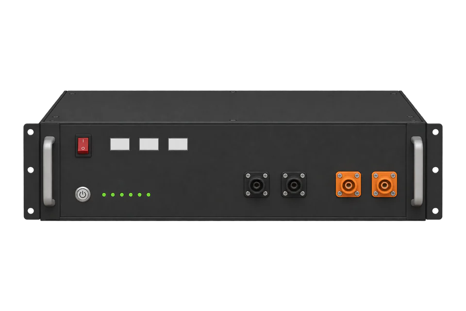
A US5000 bank on a Victron system, with the master module's CAN port wired to the GX
- Wired
- Edge
- Platforms
Models
| Models | Interface | Route into Edge |
|---|---|---|
| US5000 | 48 V, 4.8 kWh, 39.7 kg; CAN and RS485 on the front panel; no breaker | Read through the GX battery service. Victron's type A cable ASS030710018 connects the master module. |
| US5000-B | Same module with a 125 A breaker (type C, 60 V DC), 40 kg | Same GX route and cable. |
| US2000, US3000 and UP2500 | Earlier modules on Victron's type B cable ASS030720018 | Same GX route with their own cable and sizing. In a mixed bank, a US5000 is the master. |
Specifications
Each US5000 is a 48 V LFP module with 4800 Wh nominal and 4560 Wh usable at 95 % depth of discharge. Up to 16 modules form one battery group: the master is the module with an empty Link Port 0, with up to 15 slaves behind it.1
- Energy
- 4800 Wh nominal, 4560 Wh usable, 95 % depth of discharge1
- Voltage
- 48 V DC nominal; discharge 43.5 to 53.5 V; charge 52.5 to 53.5 V1
- Current
- 80 A recommended, 100 A maximum continuous; peak 101 to 120 A for 15 min and 121 to 200 A for 15 s; derating outside 10 to 40 °C cell temperature1
- Group size
- Up to 16 modules in one battery group; more groups through RS485 or an LV-HUB on CAN1
- Communication
- RS485 and CAN; DIP 1 sets RS485 at 9600 or 115200 bit/s, DIP 2 the CAN termination1
- Temperature
- 0 to 50 °C charge, -10 to 50 °C discharge, -20 to 45 °C shelf1
- Mechanical
- 442 x 420 x 161 mm, 19-inch rack, IP20, natural cooling; 39.7 kg (US5000), 40 kg (US5000-B)1
- Standards
- IEC62619, IEC63056, UL1973, UL9540A, IEC61000-6-2, IEC61000-6-3, UN38.31
- Victron minimum firmware
- GX Venus OS v3.50 for new systems; VE.Bus firmware 4692
Interface
Documented measurements and integration boundaries for US5000.
- GX battery service, the unit ID shown under Available services, FC03 or FC04: battery voltage 259 (U16, scale 100, V DC), current 261 (S16, scale 10, A DC; positive charging, negative discharging), battery temperature 262 (S16, scale 10, °C) and SOC 266 (U16, scale 10, %).
- BMS values on the same service: SOH 304 (U16, scale 10, %), max charge voltage 305 (U16, scale 10, V DC), max charge current 307 and max discharge current 308 (U16, scale 10, A DC), capacity 309 (U16, scale 10, Ah), and minimum and maximum cell temperature 318 and 319 (S16, scale 10, °C). The register list marks 304 to 308 as supported by third-party CAN-bus batteries.
- Battery power 256 is int32 in W. Registers the list marks 'Not supported by CAN.Bus BMS batteries', such as history, charge cycles and time to go, have no value for a US5000 bank.
- The GX shows all modules on the CAN link as one battery entry, so these values describe the bank, not each module. Module-level data stays in Pylontech's tools.
- DVCC charge limits, inverter settings and the battery relay are control. Edge reads only; leave writes disabled on the GX and change nothing the BMS enforces.
Assessment
US5000 and US5000-B, operation manual V1.0, on a Victron GX with Venus v3.50 or later and GX register list 3.81. Other inverter brands, module-level data and charge control are outside this scope.
- InteroperabilitySupported with conditions
- Victron documents the US5000 on the GX over CAN-bus and publishes the battery service registers, so the route is documented end to end. It needs the GX in the path.24
- AccuracySupported with conditions
- Voltage, current, SOC and limits have stated scales and a current sign. They are BMS values for the whole bank; history and time-to-go registers are not supported for CAN-bus batteries.4
- SecurityLimited
- GX Modbus TCP is off by default, but once on it reads and writes connected devices with no client authentication described. Keep it on a protected network.3
- ReliabilitySupported with conditions
- The GX returns distinct errors for a missing register, a unit ID with no device behind it and an unknown unit ID, and shows the last error in its menu.3
- RuggednessLimited
- The module is IP20 for indoor rack mounting, with charging limited to 0 to 50 °C and current derating outside 10 to 40 °C cell temperature.1
Setup
Read a US5000 bank through the GX battery service
A read-only start from GX Modbus TCP register list 3.81 for a US5000 bank already visible on the GX. Edge connects to the GX; the US5000 CAN link is the upstream battery connection. PDUs omit the MBAP header, and the response bytes are synthetic decoder checks, not captures.
- Endpoint and unit
- GX IP address, with the unit ID that Settings, Services, Modbus/TCP, Available services lists for the battery service. Unit 100 is the system service, which has its own SOC register; do not mix the two.
- Function and address convention
- FC03; the GX manual says FC03 and FC04 behave the same. Register list addresses are sent as written: SOC 266 is 0x010A, with no offset.
- SOC
- PDU 03 01 0A 00 01. Synthetic response PDU 03 02 02 F3: U16 755, scale 10, so 75.5 %.
- Voltage
- PDU 03 01 03 00 01 reads 259. Synthetic data 14 50 is U16 5200, scale 100, so 52.00 V, inside the 43.5 to 53.5 V discharge range.
- Current and direction
- PDU 03 01 05 00 01 reads 261. Synthetic data FF 83 is S16 -125, scale 10, so -12.5 A: negative means discharging in the register list.
- BMS charge limit
- PDU 03 01 33 00 01 reads max charge current 307. Synthetic data 03 E8 is 1000, scale 10, so 100.0 A. This is the limit the BMS sends over CAN, which the GX applies through DVCC.
Acceptance: This reads the US5000 bank through the Victron GX that manages it. It is not a direct Pylontech network interface or a physical Edge test, and DVCC, charge limits and the CAN link stay under the battery system's control.
-
Build the bank to Pylontech's rules
Link the modules through their link ports; the module with an empty Link Port 0 is the master, with up to 15 slaves. Use Pylontech's manual for cabling, breakers and start-up. In a mixed bank, a US5000 takes the master position.
-
Connect the master to the GX
Plug the Battery BMS end of Victron's type A cable ASS030710018 into the master's CAN port and the Victron VE.Can end into the GX's BMS-Can port. On a GX with only VE.Can ports, set that port to the CAN-bus BMS (500 kbit/s) profile and fit a VE.Can terminator. Victron requires the address DIP switches at 000 unless an LV-Hub is used.
-
Confirm the battery on the GX
The bank appears as one battery in the GX device list. From GX v2.80, DVCC settings for Pylontech are set automatically on the BMS-Can port. Do not continue until the battery shows normal values; without the CAN link the battery turns itself off.
-
Enable read access for Edge
Modbus TCP is disabled by default: enable it under Settings, Services. Note the battery's unit ID under Settings, Services, Modbus/TCP, Available services. Put the Gateway on the GX's protected network.
-
Read and compare
Read SOC 266, voltage 259 and current 261 as the worked read shows, then compare them with the GX battery page at the same time. Treat exception 0x0A or 0x0B as a missing battery service, not an empty battery.
Common questions
- Why does the GX show one battery for many modules?
- Victron's integration page says a single entry represents all batteries on the CAN link. SOC, voltage and current on the GX describe the whole bank.2
- Which cable joins a US5000 to a GX device?
- Victron's VE.Can to CAN-bus BMS type A cable, part ASS030710018, from the master module's CAN port to the GX. Pylontech's own communication cable cannot be used for that link.2
- Which register gives the bank's SOC?
- Register 266 on the battery service's unit ID, U16 with scale 10, so 755 reads 75.5 %. The system service at unit 100 has its own SOC register with a different scale, so read the one that matches the unit ID.34
- Can Edge change the charge current?
- No. The BMS sets the charge and discharge limits over CAN and the GX enforces them through DVCC. This guide reads values only.2
Related devices
Sources
- US5000 series Operation Manual (US5000, US5000-B), 5PMPA08-00219, V1.0 (opens in a new tab) (PDF)
- Victron & Pylontech US2000, US3000, US5000, US5000B and related batteries: integration guide (opens in a new tab)
- GX Modbus-TCP Manual (opens in a new tab)
- GX Modbus TCP register list 3.81 (opens in a new tab)
Further reading
Product names and trademarks belong to their owners. Publication does not imply endorsement or a commercial relationship.