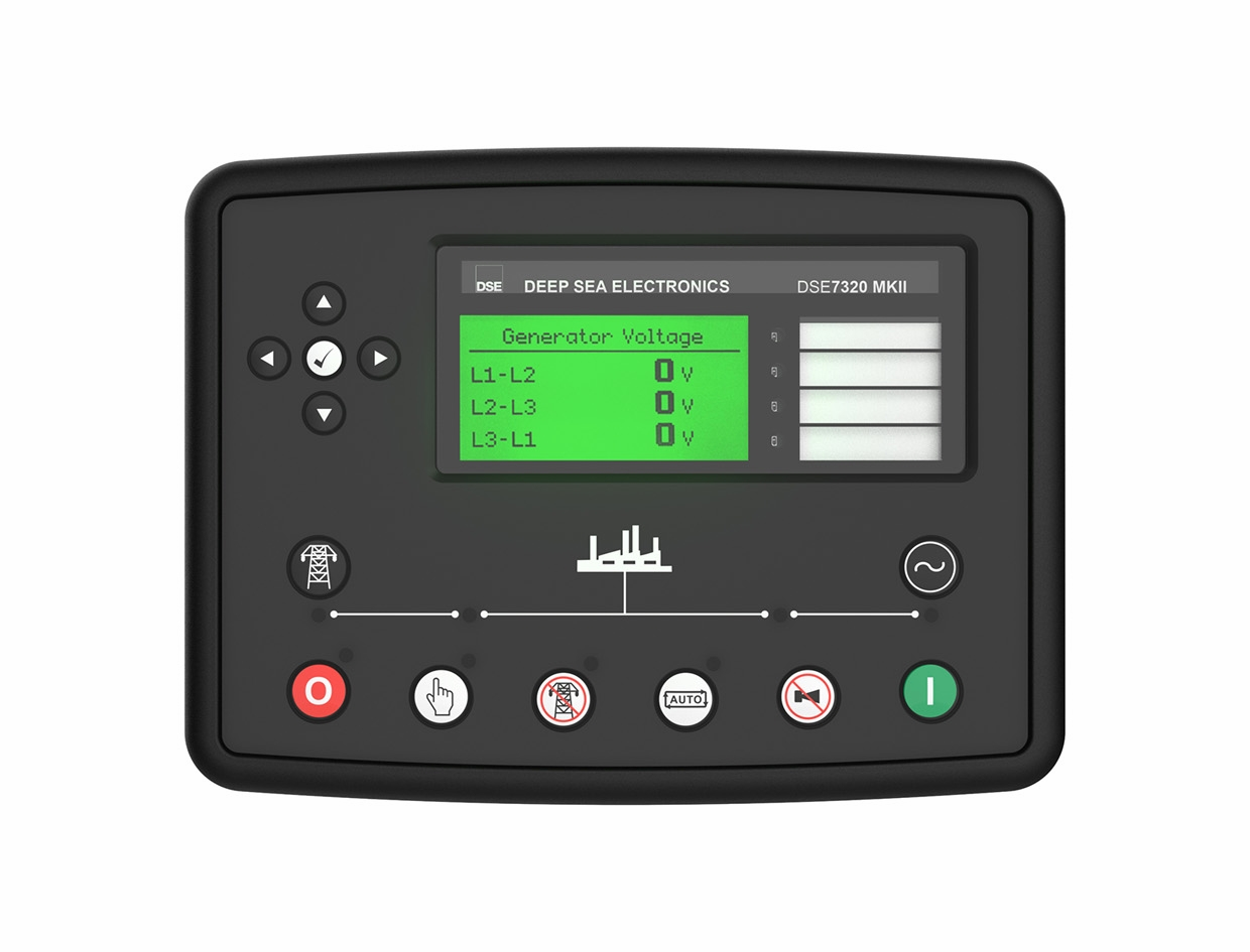
Deep Sea Electronics DSE7320 MKII
Single-generator AMF controller
DSE7320 MKII monitors both a generator and its mains supply for automatic mains-failure operation. Its integrated RS-485 Modbus RTU port is the straightforward monitoring route. USB is used for DSE Configuration Suite, and DSENet serves expansion devices.
- Modbus RTU
Single-generator AMF controller
Compatibility
Documented Modbus RTU interface
Integrated RS-232 and RS-485 Modbus RTU; DSENet is a separate expansion link
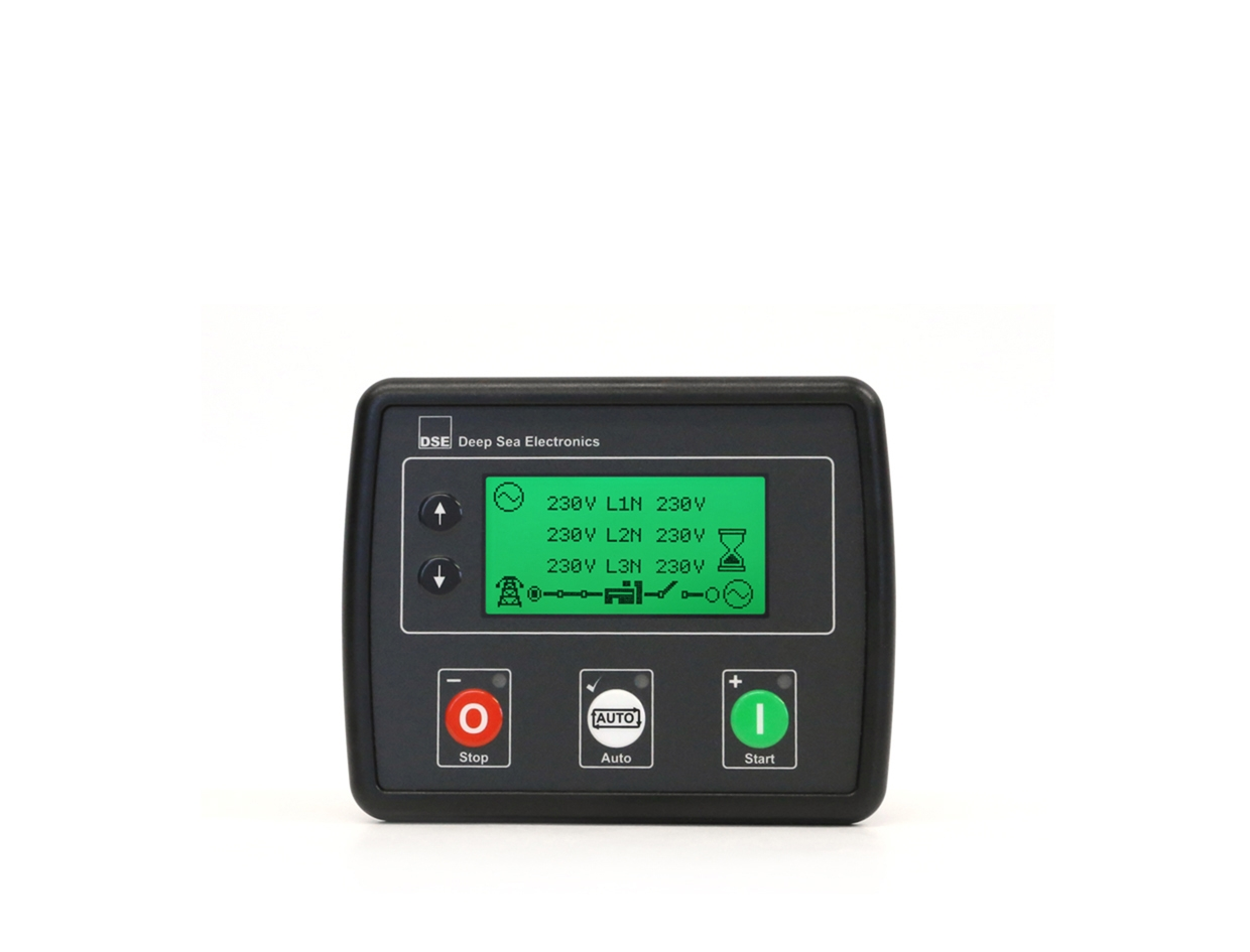
The DSE7310 MKII is the auto-start sibling. A DSE7320 MKII does not acquire native Ethernet simply because a DSE remote-communications accessory appears on the product page.
Connect it with
-
Modbus Interface ZMB-3XFrom €399 ex VAT Configure Modbus Interface
-
Gateway ZGW-20From €899 ex VAT Configure Gateway


When the documented monitoring interface is fitted and configured
- Modbus
- Edge
- Platforms
Models
| Models | Interface | Route into Edge |
|---|---|---|
| DSE7320 MKII | Integrated RS-232 and RS-485 Modbus RTU; DSENet is a separate expansion link | Save the DSE Configuration Suite file, set the RS-485 Modbus address and serial settings, and obtain the DSE Gencomm or configured page definitions for the required readings. Start with voltage, frequency and operating mode, using each published unit and scale. |
Specifications
The DSE7310 MKII is the auto-start sibling. A DSE7320 MKII does not acquire native Ethernet simply because a DSE remote-communications accessory appears on the product page.12
- Plant role
- Single-generator AMF controller1
- Monitoring and configuration
- Integrated RS-232 and RS-485 Modbus RTU; DSENet is a separate expansion link2
- Model distinction
- The DSE7310 MKII is the auto-start sibling. A DSE7320 MKII does not acquire native Ethernet simply because a DSE remote-communications accessory appears on the product page.12
- Panel protection
- IP65 front when correctly panel-mounted with the specified gasket. Check whether the gasket is supplied or an option for the exact model.2
Interface
Documented measurements and integration boundaries for DSE7320 MKII.
- Generator and mains electrical measurements, including voltage and frequency
- Engine measurements and alarm states available through the documented Modbus page definitions
- Run hours and configured status values
Assessment
Integrated RS-232 and RS-485 Modbus RTU; DSENet is a separate expansion link
- InteroperabilitySupported with conditions
- Integrated RS-232 and RS-485 Modbus RTU; DSENet is a separate expansion link12
- AccuracySupported with conditions
- The documentation identifies electrical and operating measurements for this plant role. CT configuration and measurement location determine how those values are used.12
- SecurityNot yet assessed
- The cited documentation does not establish an authenticated, encrypted Edge monitoring connection.
- ReliabilityNot yet assessed
- The controller application distinguishes operating conditions and alarms. Retain communication availability alongside the plant readings.
- RuggednessSupported with conditions
- IP65 front when correctly panel-mounted with the specified gasket. Check whether the gasket is supplied or an option for the exact model.2
- ScalabilityNot yet assessed
- Assign one device identity per controller and keep generator, mains and busbar measurements separate.
Setup
-
Save the DSE Configuration Suite file, set the RS-485 Modbus address and serial settings, and obtain the DSE Gencomm or configured page definitions for the required readings.
Start with voltage, frequency and operating mode, using each published unit and scale.
-
Record CT ratios and the physical measurement location.
Compare the first electrical values with the controller display before using them in totals or trends.
-
Keep missing responses distinct from a stopped generator.
Store communication availability beside running state so a disconnected cable does not look like healthy standby.
-
Build a read-only point list for monitoring.
Remote start, synchronisation and breaker operation require a separate control design with the existing panel interlocks and feedback.
Related devices
Sources
Further reading
Product names and trademarks belong to their owners. Publication does not imply endorsement or a commercial relationship.