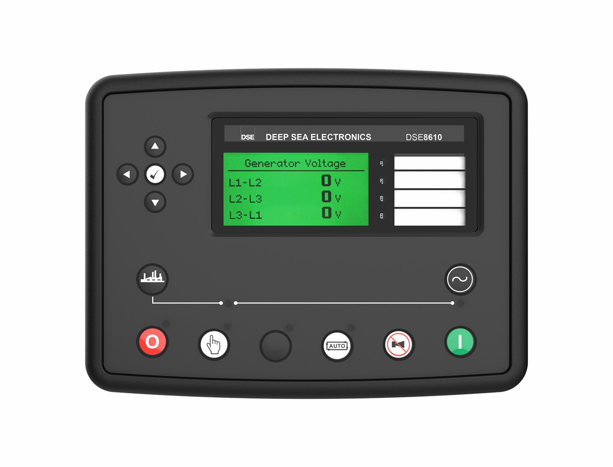
Deep Sea Electronics DSE8610 MKII
Generator paralleling controller
DSE8610 MKII synchronises and shares load between generating sets. It supports generator-to-generator systems of up to 32 sets and provides serial and Ethernet monitoring. The MSC plant-control link and engine CAN link remain separate from the BMS Modbus connection.
- Modbus RTU
- Modbus TCP
Generator paralleling controller
Compatibility
Documented Modbus RTU and TCP interface
RS-485 Modbus RTU and Ethernet Modbus TCP; CAN and MSC links have separate control roles
The product page reserves the second RS-485 port for a future update, so use the commissioned active port. DSE8620 MKII additionally serves generator-to-mains AMF applications; do not interchange plant roles.
Connect it with
-
Modbus Interface ZMB-3XFrom €399 ex VAT Configure Modbus Interface
-
Gateway ZGW-20From €899 ex VAT Configure Gateway


When the documented monitoring interface is fitted and configured
- Modbus
- Edge
- Platforms
When the documented monitoring interface is fitted and configured
- Modbus
- Edge
- Platforms
Models
| Models | Interface | Route into Edge |
|---|---|---|
| DSE8610 MKII | RS-485 Modbus RTU and Ethernet Modbus TCP; CAN and MSC links have separate control roles | Save the DSE Configuration Suite file and record the controller identity in the load-share system. Select the active monitoring port, export configured Modbus pages and compare per-generator measurements before calculating plant totals. |
Specifications
The product page reserves the second RS-485 port for a future update, so use the commissioned active port. DSE8620 MKII additionally serves generator-to-mains AMF applications; do not interchange plant roles.12
- Plant role
- Generator paralleling controller1
- Monitoring and configuration
- RS-485 Modbus RTU and Ethernet Modbus TCP; CAN and MSC links have separate control roles2
- Model distinction
- The product page reserves the second RS-485 port for a future update, so use the commissioned active port. DSE8620 MKII additionally serves generator-to-mains AMF applications; do not interchange plant roles.12
- Panel protection
- IP65 front when correctly panel-mounted with the specified gasket. Check whether the gasket is supplied or an option for the exact model.2
Interface
Documented measurements and integration boundaries for DSE8610 MKII.
- Per-generator voltage, frequency, current and electrical power
- Engine measurements, operating mode and alarms
- Breaker and synchronisation status in the configured Modbus pages
Assessment
RS-485 Modbus RTU and Ethernet Modbus TCP; CAN and MSC links have separate control roles
- InteroperabilitySupported with conditions
- RS-485 Modbus RTU and Ethernet Modbus TCP; CAN and MSC links have separate control roles12
- AccuracySupported with conditions
- The documentation identifies electrical and operating measurements for this plant role. CT configuration and measurement location determine how those values are used.12
- SecurityNot yet assessed
- The cited documentation does not establish an authenticated, encrypted Edge monitoring connection.
- ReliabilityNot yet assessed
- The controller application distinguishes operating conditions and alarms. Retain communication availability alongside the plant readings.
- RuggednessSupported with conditions
- IP65 front when correctly panel-mounted with the specified gasket. Check whether the gasket is supplied or an option for the exact model.2
- ScalabilityNot yet assessed
- Assign one device identity per controller and keep generator, mains and busbar measurements separate.
Setup
-
Save the DSE Configuration Suite file and record the controller identity in the load-share system.
Select the active monitoring port, export configured Modbus pages and compare per-generator measurements before calculating plant totals.
-
Record CT ratios and the physical measurement location.
Compare the first electrical values with the controller display before using them in totals or trends.
-
Keep missing responses distinct from a stopped generator.
Store communication availability beside running state so a disconnected cable does not look like healthy standby.
-
Build a read-only point list for monitoring.
Remote start, synchronisation and breaker operation require a separate control design with the existing panel interlocks and feedback.
Related devices
Sources
Further reading
Product names and trademarks belong to their owners. Publication does not imply endorsement or a commercial relationship.